
C-arm system with extended field of view

Active Publication Date: 2014-10-30
KONINKLJIJKE PHILIPS NV
View PDF1 Cites 12 Cited by
  • Summary
  • Abstract
  • Description
  • Claims
  • Application Information

AI Technical Summary

Benefits of technology

The patent is about C-arm systems that can have a wider range of motion and require less effort to move. This allows for better accuracy in reconstructing the position of an object.

Problems solved by technology

For imaging procedures on a C-arm system providing tomographic X-ray image data, which procedures are also referred to as CT-like imaging procedures, this limitation is of disadvantage when the area of interest is not completely covered by the three-dimensional field of view.
However, the detector has to be provided to be shiftable, requiring mechanical means to allow the displacement.

Method used


Image

  • C-arm system with extended field of view
  • C-arm system with extended field of view
  • C-arm system with extended field of view

Examples


Embodiment Construction

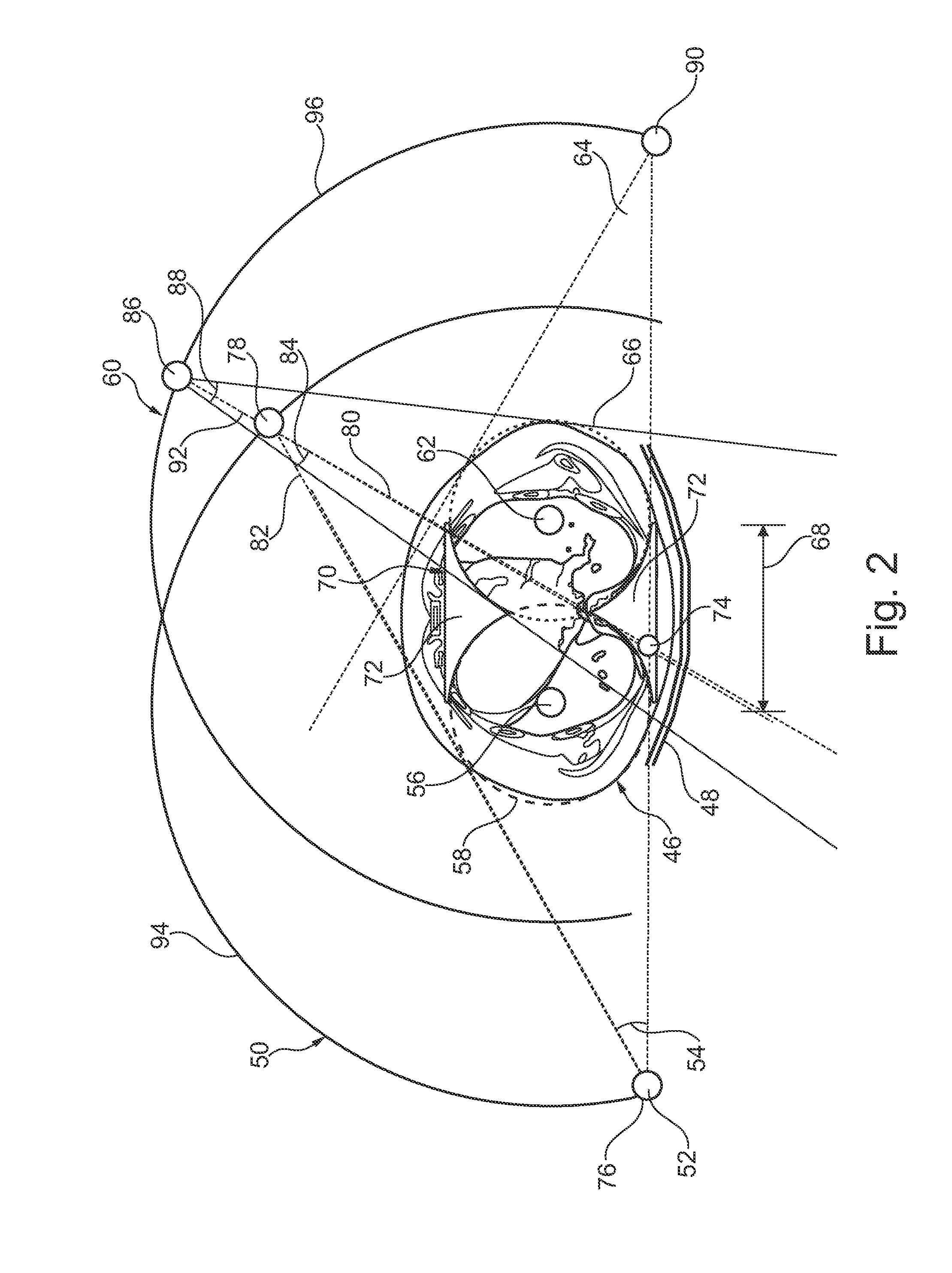
[0055]As indicated above, the present invention proposes an acquisition and reconstruction method to realize an extended field of view (XFOV) from two arc acquisitions, for example from two circular arc acquisitions. The invention comprises two or more arc acquisitions, for example circular arc acquisitions, with a displaced, for example shifted, ISO-centre between the acquisitions, wherein the first and the second ISO-centre are displaced in relation to each other such that a connection line between the first and the second ISO-centre is arranged transverse to the first and the second axis of rotation. The ISO-centre displacement, e.g. shift can be realized either by a displacement of the whole C-arm system or by displacing the patient table, or by a combination of both.

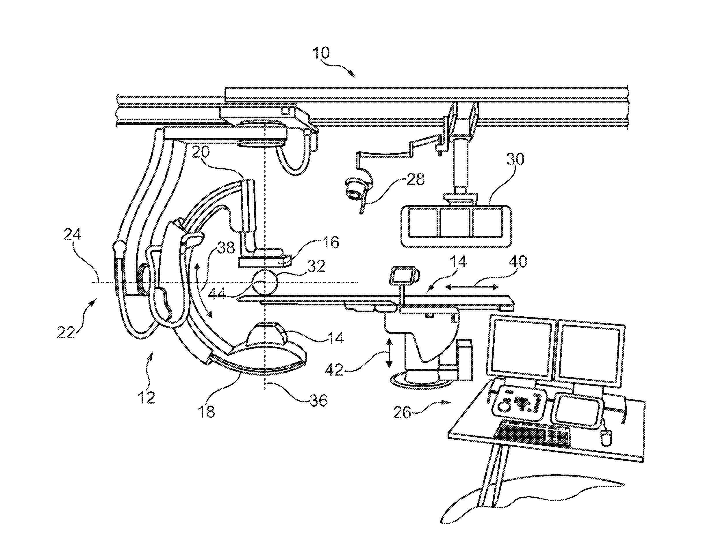
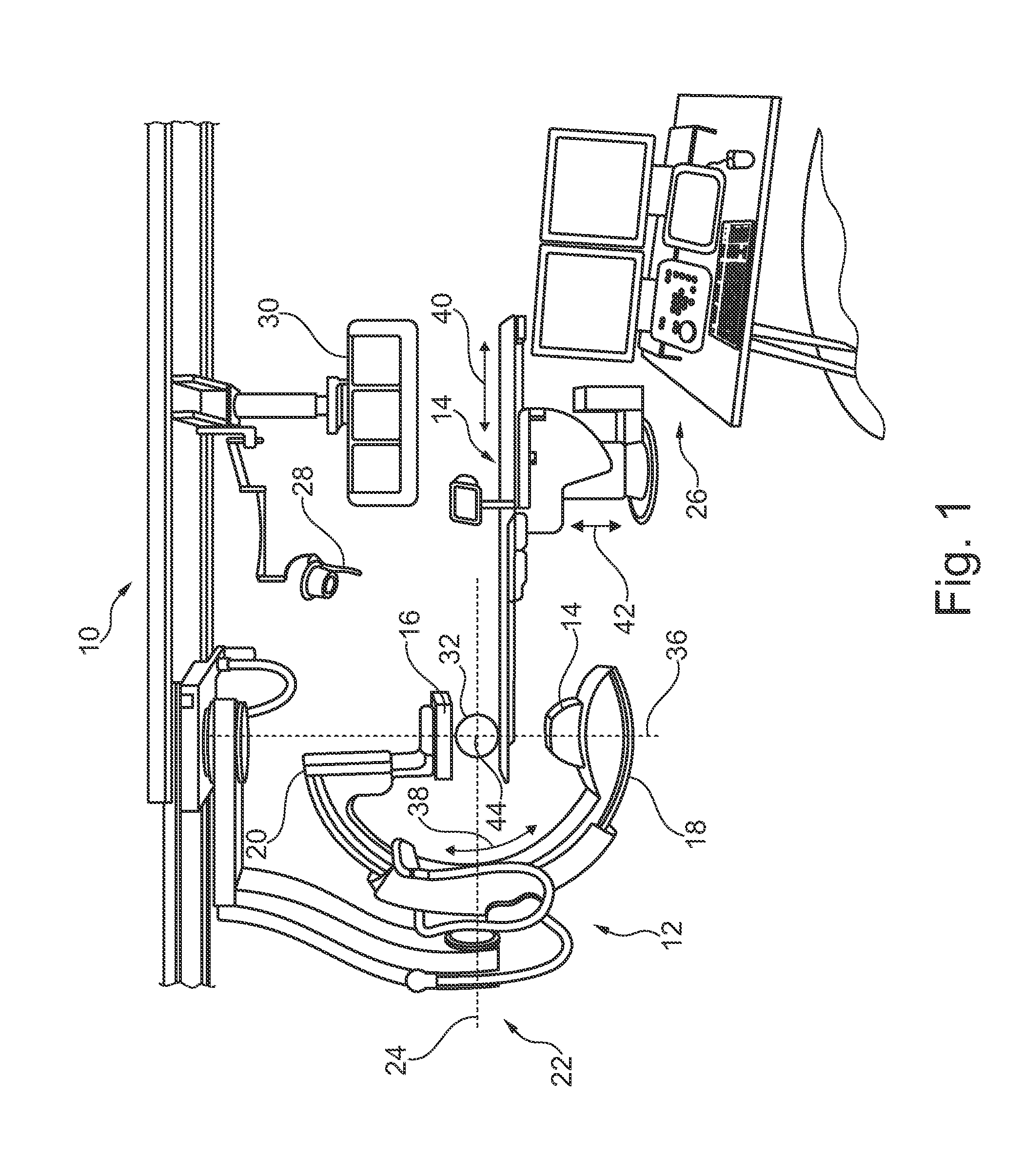
[0056]FIG. 1 shows a C-arm X-ray imaging system 10 comprising a C-arm structure 12 with an X-ray source 14 and an X-ray detector 16 mounted across from the X-ray source, i.e. on opposing ends 18, 20 of the C-arm. Fu...


PUM


Abstract

The present invention relates to a C-arm X-ray imaging system. In order to provide C-arm systems with an extended three-dimensional field of view, a C-arm X-ray imaging system (10), provided to acquire extended three-dimensional images of an object, is provided, comprising a C-arm structure (12) with an X-ray source (14) and an X-ray detector (16) mounted across from the X-ray source, a motorized drive (22) for a rotational movement of the C-arm structure, and a control unit (26). The C-arm structure is provided to perform a rotational scan around an axis of rotation and around an ISO-centre acquiring a number of X- ray projections in order to generate image data for a reconstructed three-dimensional field of view. The control unit is configured to control the motorized drive, and to cause the rotational movement of the C-arm structure to perform a first rotational X-ray scan (50) around a first ISO-centre (56) with a first axis of rotation for a first field of view, and to perform at least a second rotational X-ray scan (60) around a second ISO-centre (62) with a second axis of rotation for a second field of view. The first and the second centre of rotation are displaced in relation to each other such that a connection line between the first and the second ISO-centre is arranged transverse to the first and the second axis of rotation.

Description

FIELD OF THE INVENTION[0001]The present invention relates to a C-arm X-ray imaging system, a method for acquiring 3D X-ray image data of an object, as well as to a computer program element and a computer readable medium.BACKGROUND OF THE INVENTION[0002]In a C-arm system, the three-dimensional field of view is limited by the geometrical arrangement of the distance between source and detector and the detector size itself. For imaging procedures on a C-arm system providing tomographic X-ray image data, which procedures are also referred to as CT-like imaging procedures, this limitation is of disadvantage when the area of interest is not completely covered by the three-dimensional field of view. For example, in operational interventions in relation with the liver, for example in hypervascular liver lesion treatment, the region of interest may not be fully covered by the three-dimensional field of view. US 2011 / 0255657 A1 relates to CT image acquisition and describes the lateral displace...

Claims


Application Information

Patent Timeline
IPC IPC(8): A61B6/02
CPCA61B6/022A61B6/032A61B6/4441A61B6/588A61B6/5205
Inventor SCHAFER, DIRKGRASS, MICHAEL
Owner KONINKLJIJKE PHILIPS NV
Learn More