

Apparatus and method to prevent side channel power attacks in advanced encryption standard using floating point operation
- Summary
- Abstract
- Description
- Claims
- Application Information
AI Technical Summary
Benefits of technology
Problems solved by technology
Method used
Image

Examples
Embodiment Construction
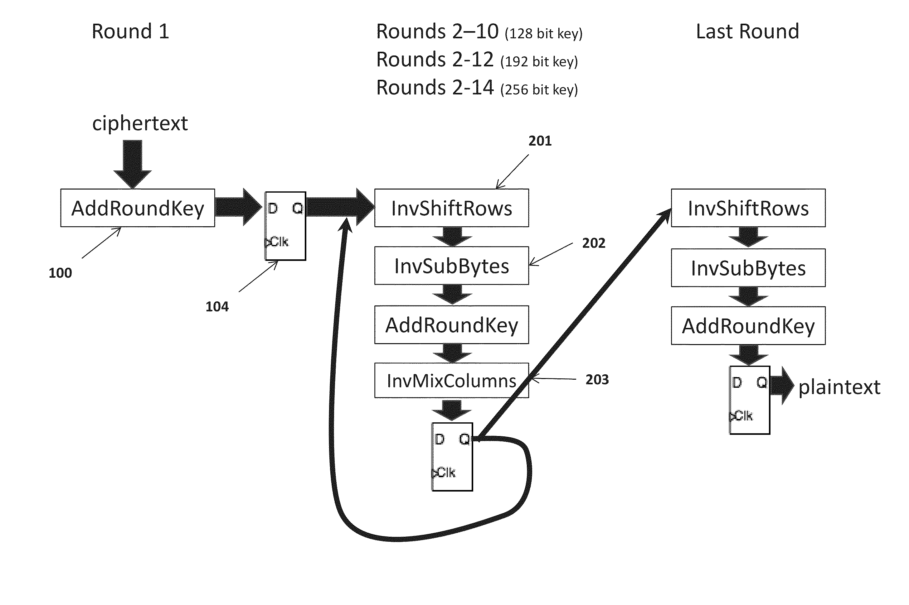
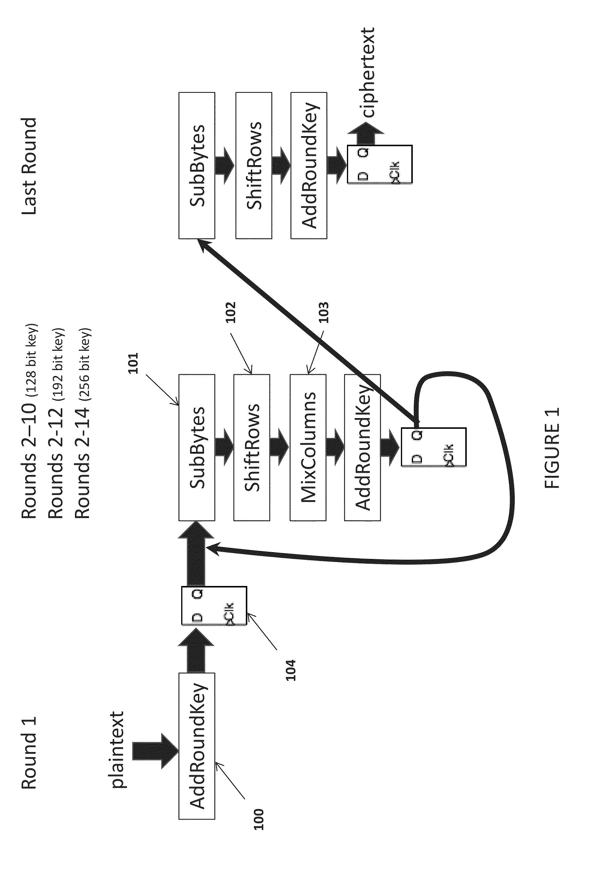
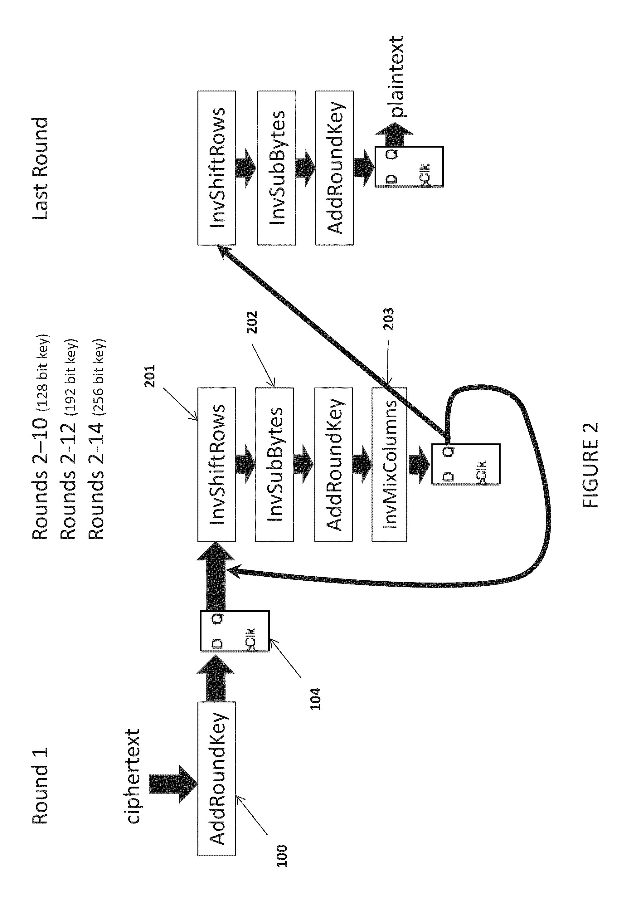
[0019]Referring to FIG. 1, round 1 as specified by the algorithm leaves the key vulnerable to side channel power attacks when the algorithm is implemented in hardware. Round 1 only executes the AddRoundKey 100 transformation, or an exclusive or operation of the and data (see FIG. 3). In order to obfuscate the power consumption during round 1 execution, the present invention also uses the plaintext data input as an input to a processor floating point unit.
[0020]Referring to FIG. 4, the present invention's physical implementation in the Advanced Encryption Standard (AES) process is schematically depicted. The plaintex data is not only input to the AddRoundKey 100 transformation but is also simultaneously used as input to a processor floating point unit 401 and latched in flip flop 402. The floating point operation obfuscate the power consumption of the AddRoundKey 100 due to the new plurality of lower level gates that will be exercised during the floating point unit operation. The pre...
PUM
 Abstract
Description
Claims
Application Information