Structure of printed circuit board of electrical connector

Inactive Publication Date: 2014-10-30
KINNEXA
View PDF10 Cites 3 Cited by
  • Summary
  • Abstract
  • Description
  • Claims
  • Application Information

AI Technical Summary

Benefits of technology

The present invention aims to provide a printed circuit board for an electrical connector that has excellent IEEE and EMI properties, does not have impedance matching problem, and can be efficiently and stably manufactured. The invention uses circuit boards as a bridge connection, which allows for easy and fast assembly without additional wiring and ensures stability through soldering applied to arrayed pins. This technique overcomes the manufacturing time and matching issues of conventional network connectors.

Problems solved by technology

This leads to a loss of manufacturing time and may further cause issues of matching and electromagnetic interference (due to wire stretching being varying in the manufacture that affect the EMI characteristics thereof).

Method used


Image

  • Structure of printed circuit board of electrical connector
  • Structure of printed circuit board of electrical connector
  • Structure of printed circuit board of electrical connector

Examples


Embodiment Construction

[0014]The following descriptions are exemplary embodiments only, and are not intended to limit the scope, applicability or configuration of the invention in any way. Rather, the following description provides a convenient illustration for implementing exemplary embodiments of the invention. Various changes to the described embodiments may be made in the function and arrangement of the elements described without departing from the scope of the invention as set forth in the appended claims.

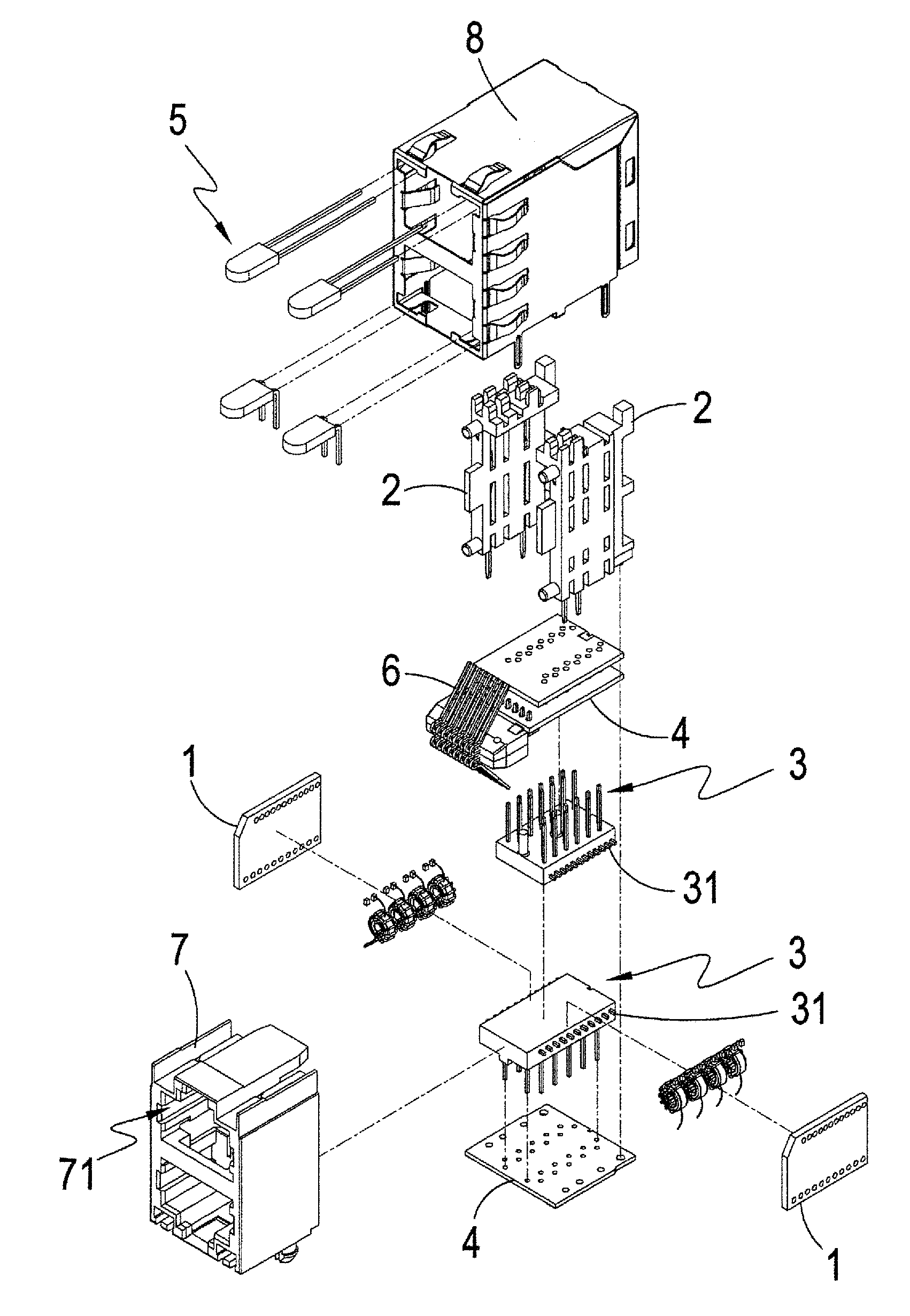
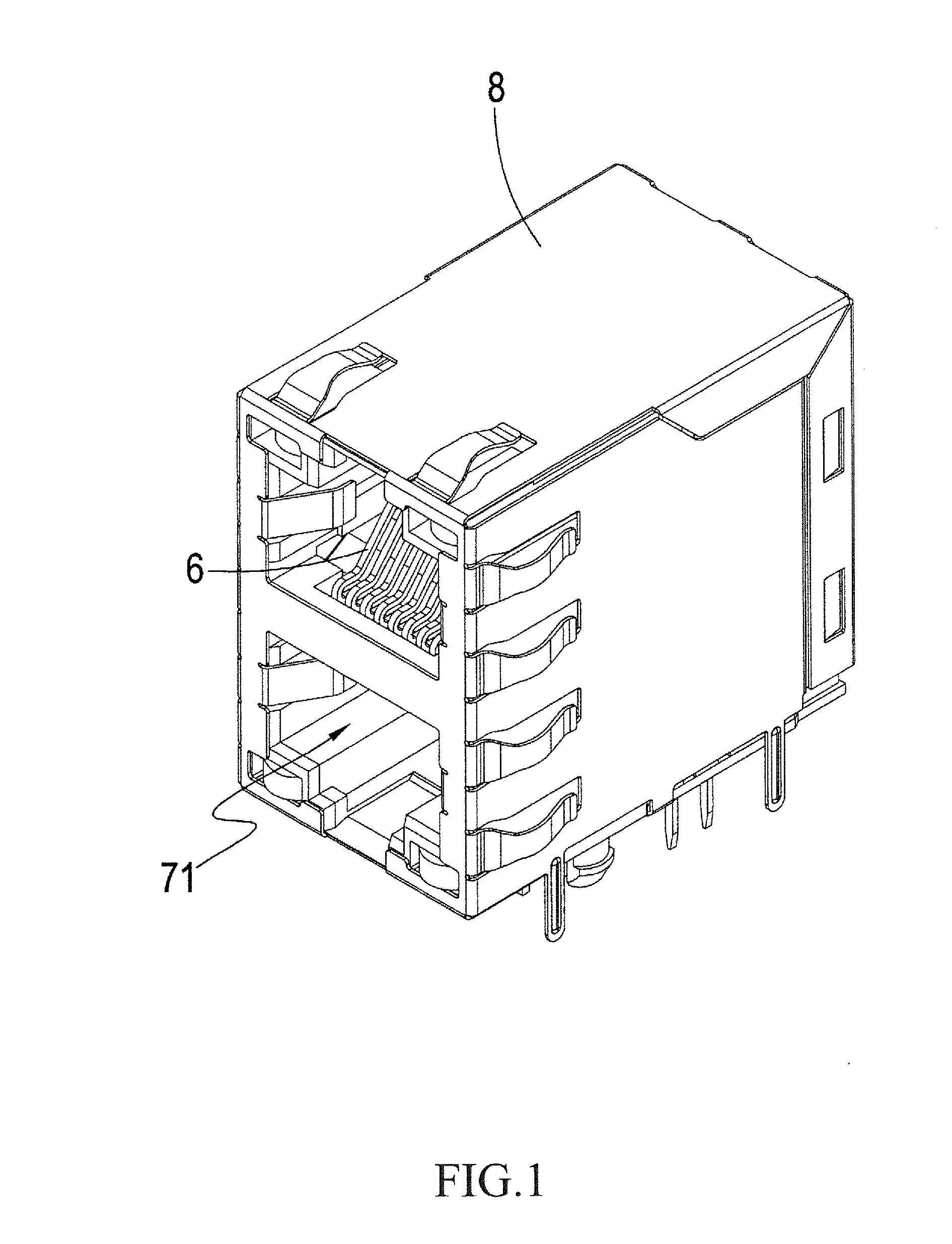
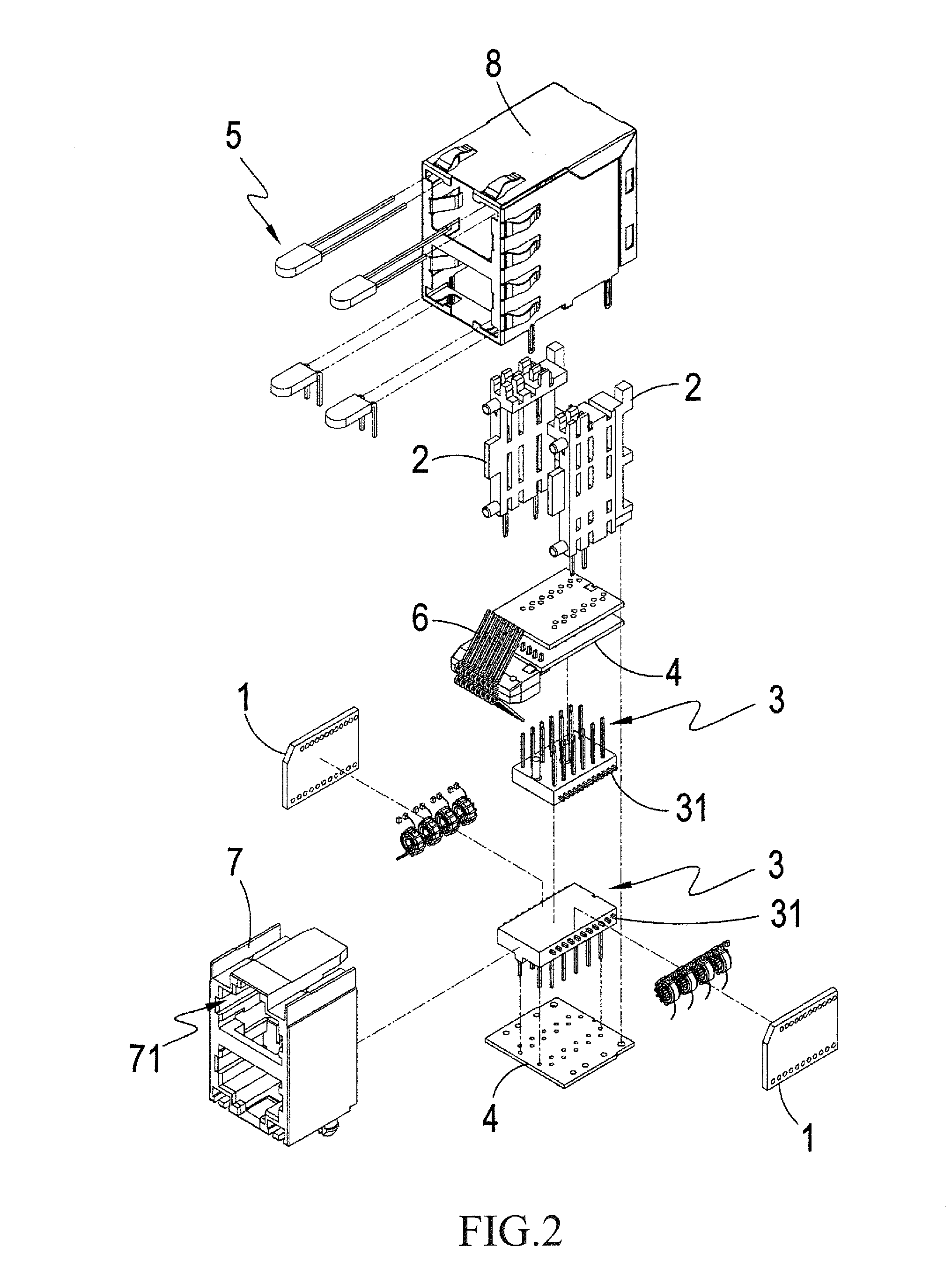
[0015]Referring to FIGS. 1-3, which are respectively a perspective view and an exploded view of a preferred embodiment of the present invention, and a schematic view showing a portion of the preferred embodiment of the present invention, these drawings clearly show that the present invention comprises:

[0016]a plurality of circuit boards 1, which provides a network signal transmission matching function and is each a printed circuit board, wherein the circuit boards 1 are each provided, at least at on...


PUM


Abstract

A structure of a printed circuit board of an electrical connector generally includes a plurality of circuit boards, which provides a network signal transmission matching function and a plurality of coupling modules, which includes arrayed pins embedded therein. Each of the circuit boards is fixedly mounted to one side of each of the coupling modules and is electrically connected to ends of the arrayed pins and forms a channel. As such, the technical feature of the present invention that uses circuit boards to serve as bridge connection allows the circuit boards to be assembled to the coupling modules in such a way that additional wiring is not needed and connection can be established through soldering applied to the arrayed pins, thereby achieving the advantages that assembling can be carried out in an easy, fast, and time-efficient manner.

Description

TECHNICAL FIELD OF THE INVENTION[0001]The present invention generally relates to an electrical connector, and more particularly to a structure of a printed circuit board of an electrical connector that shows excellent IEEE and EMI properties, has no impedance matching problems, and can be efficiently and stably manufactured.DESCRIPTION OF THE PRIOR ART [0002]Due to diversity of manufacturing technology of different manufacturers, network connectors manufactured are often of difference in the final products thereof, but still in compliance with the standards and requirements of communication protocol issued by related associations and communities, such as IEEE (Institute of Electrical and Electronics Engineers) and EMI (Electro-Magnetic Interference). To improve performance and obtain enhanced effect, all manufacturers are devoted themselves to the research and improvement of network connector and makes trials on various combinations of different electronic components, while keeping ...

Claims


Application Information

Patent Timeline
IPC IPC(8): H01R12/71
CPCH01R12/716H01R13/6466H01R13/6658H01R13/7175H01R24/64
Inventor WEI, KUAN-HSIUNG
Owner KINNEXA
Why Eureka
Try Eureka