Vehicle engine-starting device

Active Publication Date: 2014-10-30
TOYOTA JIDOSHA KK
View PDF2 Cites 2 Cited by
  • Summary
  • Abstract
  • Description
  • Claims
  • Application Information

AI Technical Summary

Benefits of technology

The present invention provides an engine-starting device for a vehicle that includes a drive plate, an electric motor with a pinion, and an actuator for moving the pinion to engage or disengage with the drive plate. The device also includes a parking lock mechanism that can be switched between a position that permits rotation of the output shaft of the automatic transmission and a position that inhibits rotation. The use of an electric motor as the drive power source for both the engine-starting and the parking lock mechanism reduces the number of electric motors in the engine room, resulting in a lighter vehicle and more space within the engine room. Additionally, the actuator can be operated to move the pinion to the non-engaging position for disengagement from the drive plate, even if the manual shaft has a failure to switch between the rotation permitting and parking lock positions. This allows for improved flexibility in dealing with the failure.

Problems solved by technology

However, an electric motor of the vehicular engine-starting device arranged as described above is used only when the engine is started, but is not utilized for another purpose, for example, as the parking lock electric motor or the oil pump driving electric motor, so that the weight of the vehicle is increased, and the number of the electric motors disposed within the engine room is increased, leading to a problem of reduction of a space available within the engine room.

Method used


Image

  • Vehicle engine-starting device
  • Vehicle engine-starting device
  • Vehicle engine-starting device

Examples


first embodiment

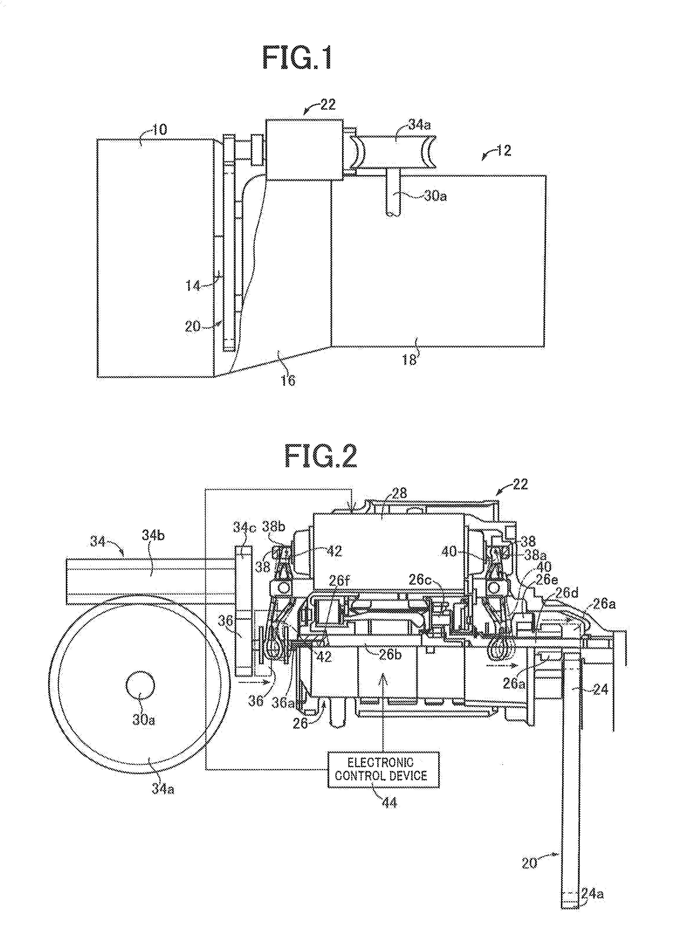
[0027]FIG. 1 is the schematic view showing an engine 10 provided on a vehicle to which the present invention is applicable, and a power transmitting system 12 for transmitting a drive force of the engine 10 to a pair of drive wheels not shown. An output of the engine 10 which is an internal combustion engine provided as a vehicle drive power source is transmitted to the pair of drive wheels through a crankshaft 14 of the engine 10, a torque converter 16, an automatic transmission 18 and a differential gear device.

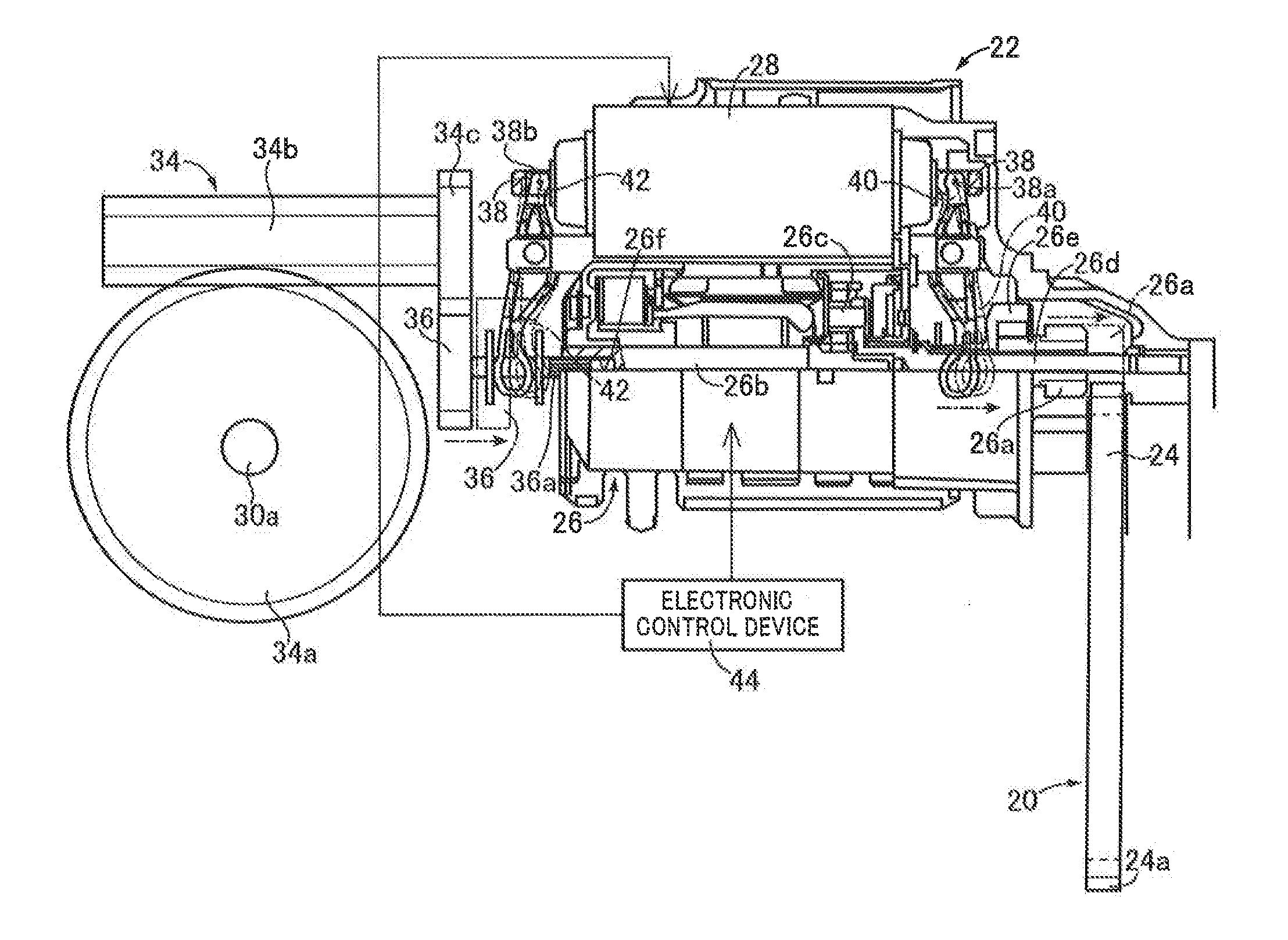
[0028]The power transmitting system 12 is provided with an engine starting device 22 configured to start the engine 10, namely, to raise an operating speed of the engine 10 to a value at which the engine 10 is operable by itself. As shown in FIG. 2, this engine starting device 22 is provided with a drive plate 20, a starter motor (electric motor) 26, and an actuator device 28 of a magnet (electromagnet) type. The drive plate 20 is provided with an annular starter ring gear ...

second embodiment

[0047]Other embodiments of this invention will be described. It is to be understood that the same reference signs will be used to identify the corresponding elements in the different embodiments, which will not be described redundantly.

[0048]An engine-starting device 58 according to the present embodiment is different from the engine-starting device 22 according to the above-described first embodiment, in that the engine-starting device 58 is provided with an actuator device 60 different from the actuator device 28 of the first embodiment. In the other aspects, the engine-starting device 58 is substantially identical in construction with the engine-starting device 22.

[0049]As shown in FIG. 7, the actuator device 60 consists of a first switching device 62 configured to move the first pinion 26a between the engaging position for engagement with the starter ring gear 24 and the non-engaging position for disengagement from the starter ring gear 24, and a second switching device 64 confi...

third embodiment

[0057]An engine-starting device 70 according to the present third embodiment is different from the engine-starting device 58 according to the second embodiment, in that the starter motor 26 is utilized to drive an oil pump 72 to deliver a working oil used by the automatic transmission 18. In the other aspects, the engine-starting device 70 is substantially identical in construction with the engine-starting device 58.

[0058]As shown in FIG. 9, the oil pump 72 is an internal-gear type oil pump provided with an annular driven gear 74 disposed rotatably within an oil chamber, and a drive gear 76 which has external teeth meshing with internal teeth of the driven gear 74 and which is rotatably disposed about its axis of rotation eccentric with respect to an axis of rotation of the driven gear 74, to rotate the driven gear 74.

[0059]As shown in FIG. 9, the oil pump 72 is provided with an input shaft 78 in the form of a cylinder fixed to the drive gear 76, and a connecting shaft 80 one end po...


PUM


Abstract

An engine-starting device for a vehicle having an engine, a parking lock mechanism and an automatic transmission, the engine-starting device being provided with a drive plate connected to a crankshaft of said engine, an electric motor having a pinion selectively engageable with the drive plate, and an actuator device configured to move said pinion to an engaging position for engagement with said drive plate to start said engine, comprises: said parking lock mechanism having a manual shaft selectively switchable between a rotation permitting position for permitting a rotary motion of an output shaft of said automatic transmission, and a parking lock position for inhibiting the rotary motion of the output shaft; and said actuator device being configured to move said pinion between said engaging position and a non-engaging position for disengagement from said drive plate, said electric motor being connected to said manual shaft to rotate the manual shaft from one of said rotation permitting position and said parking lock position to the other, when said pinion is located at said non-engaging position by said actuator device.

Description

CROSS-REFERENCE TO RELATED APPLICATIONS[0001]This application is a national phase application of International Application No. PCT / JP2011 / 076586, filed Nov. 17, 2011, the content of which is incorporated herein by reference.TECHNICAL FIELD[0002]The present invention relates to a vehicular engine-starting device, and more particularly to techniques for reducing the number of electric motors disposed within an engine room, by utilizing at least one of an electric motor of a parking lock mechanism and an electric motor of an oil pump, as an electric motor of a vehicular engine-starting device.BACKGROUND ART[0003]One type of the vehicular engine-starting device is provided with (a) a drive plate connected to a crankshaft of an engine, (b) an electric motor having a pinion selectively engageable with the drive plate, and (c) an actuator device configured to move the pinion to an engaging position for engagement with the above-described drive plate, for starting the above-described engine...

Claims


Application Information

Patent Timeline
IPC IPC(8): F02N11/00
CPCF02N11/00F02N11/003F02N15/067F16H63/3458B60Y2300/63F16H61/0031F16H61/0025
Inventor MORISE, MASARUOITA, SHINJI
Owner TOYOTA JIDOSHA KK
Why Eureka
Try Eureka