Device for defining a cutting plane for a bone resection

a cutting plane and bone resection technology, applied in the field of bone resection cutting plane devices, can solve the problems of difficult to keep such foot clamps stable, difficult to tightly secure the foot clamps, and device disclosed

Active Publication Date: 2014-10-30
WALDEMAR LINK GMBH & CO
View PDF7 Cites 11 Cited by
  • Summary
  • Abstract
  • Description
  • Claims
  • Application Information

AI Technical Summary

Problems solved by technology

It is usually quite difficult to tightly secure the foot clamp there because excessively high retaining forces cannot be applied, so as not to endanger the blood supply to the foot.
Accordingly, it is often not easy to keep such foot clamps stable and thus also, by making an adjustment in this area, to make a corresponding, accurate and precision adjustment of the angular position.
However, the device disclosed in this document is comparatively user-unfriendly, in particular with regard to the adjustment of the tilt(s) of the cutting plane(s) with respect to the slope ang

Method used


Image

  • Device for defining a cutting plane for a bone resection
  • Device for defining a cutting plane for a bone resection
  • Device for defining a cutting plane for a bone resection

Examples


Embodiment Construction

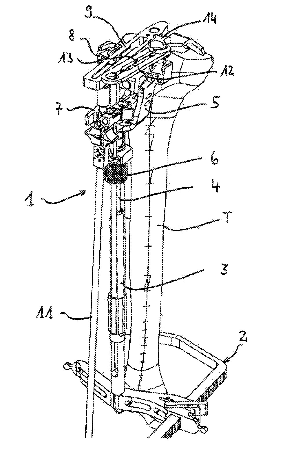
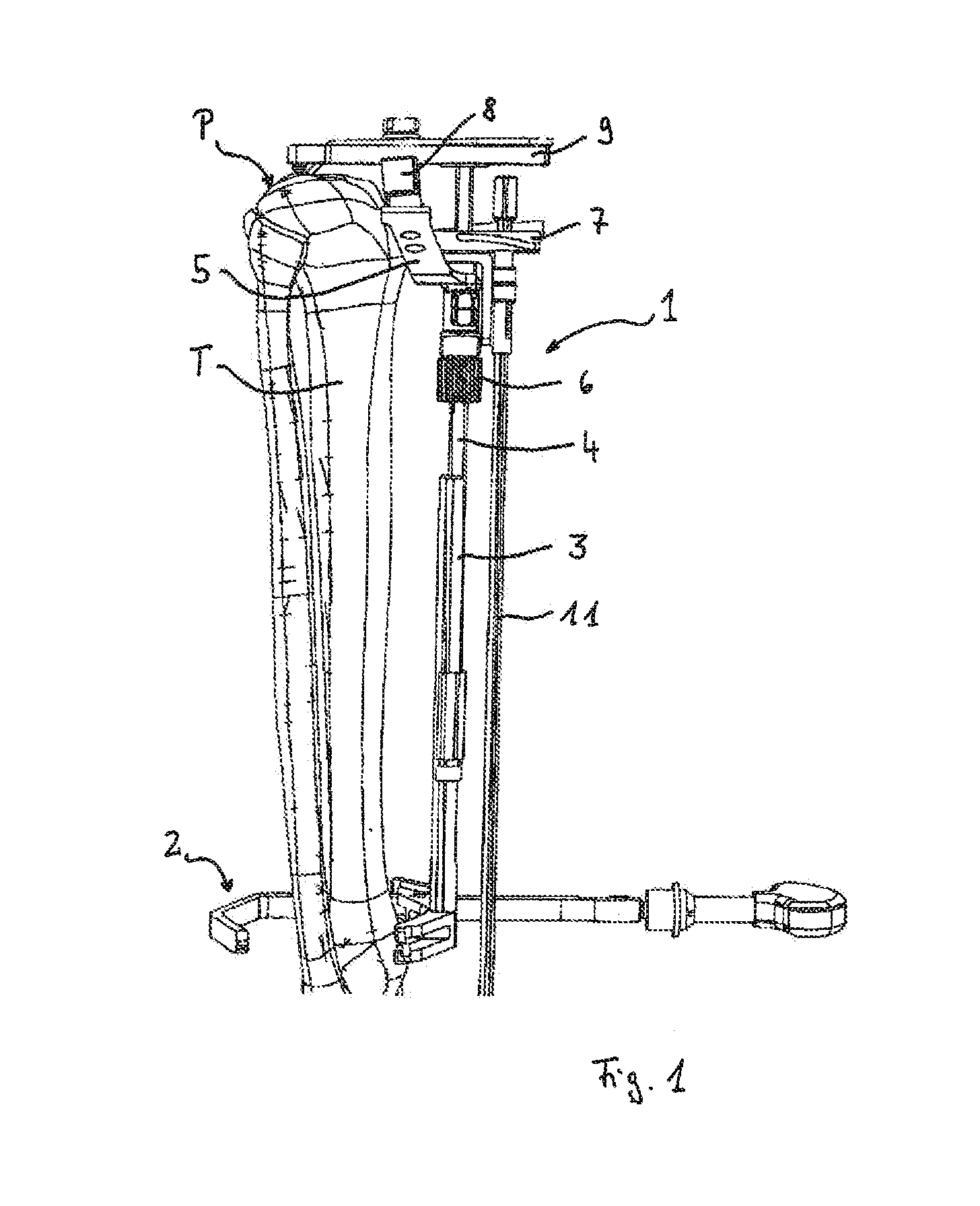
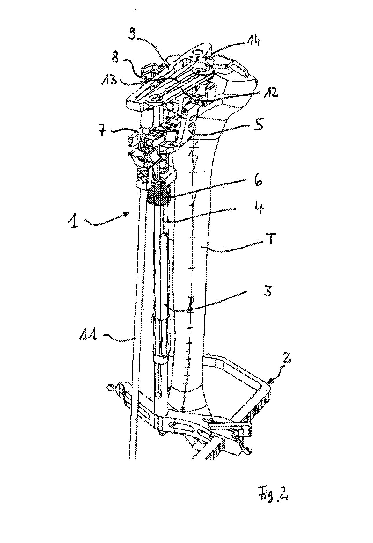
[0007]A remedy is to be created here with this invention by refining a device of the type described in the introduction and having the features of the preamble of claim 1 to the extent that the tilt mechanism is simple to operate and is reliable with regard to the accuracy of the position of the cutting plane, once its position has been set, even while performing the resection cut.

[0008]A solution to this problem is offered with the present invention through a device having the features of patent claim 1. Advantageous refinements of the device according to the invention are defined in the dependent claims 2 through 12.

[0009]The device according to the invention is thus characterized by a specially designed tilt mechanism, which has components on two elements that can be tilted about the first axis relative to one another. These elements may be the base body and / or the cut-guiding element directly, but these elements may also be and / or comprise bearing blocks that are provided for im...


PUM


Abstract

An adjustable device for defining a cutting plane for bone resection comprising a base positionable on the bone and a cut-guiding element placeable on the base. The cut-guiding element includes a cut-guiding structure for guiding a cutting tool in the cutting plane, the cut-guiding element being tiltable relative to the base about at least one first axis by an adjustable tilt mechanism to adjust the angle of the cutting plane. The tilt mechanism includes a rectilinear guide and a slide that is linearly displaceable along the guide in the longitudinal direction. The tilt mechanism includes a guide portion relative to which an effective portion of the slide is displaced; the guide portion and the effective portion having interacting structures forming a sliding guide effective at a right angle to the longitudinal direction.

Description

TECHNICAL FIELD[0001]The present invention relates to a device for defining a cutting plane for bone resection according to the preamble of claim 1.PRIOR ART[0002]In medicine, in particular for the use of joint endoprostheses in orthopedic surgery, resection cuts are made to remove the worn regions of the bones involved in the respective joint and to create a defined binding geometry for the joint endoprosthesis parts to be used. It is important for the resection cuts to be guided precisely, so that an endoprosthetic replacement will permit optimal function with regard to the geometry in which it is positioned in the patient's body and will restrict the patient as little as possible with regard to freedom of movement. This is true not only in the field of knee endoprosthesis, where appropriate care must be taken in resection of the distal femur component and the proximal tibia plateau in order not to alter the postoperative position and spatial orientation of the leg having the endo...

Claims


Application Information

Patent Timeline
IPC IPC(8): A61B17/17
CPCA61B17/1764A61B17/155A61B17/157A61F2002/4668A61B2090/067
Inventor DMUSCHEWSKY, KLAUSBALZARINI, AMOS
Owner WALDEMAR LINK GMBH & CO
Why Eureka
Try Eureka