Tunnel excavation device

Active Publication Date: 2014-11-06
KOREA RAILROAD RES INST
View PDF4 Cites 16 Cited by
  • Summary
  • Abstract
  • Description
  • Claims
  • Application Information

AI Technical Summary

Benefits of technology

[0018]According to the present invention, when an excavation work is performed, the bedrock is crushed by forming holes using perforating means such as laser drills, and injecting water and liquefied nitrogen into the holes, thereby reducing vibrations, noises and dust in the vicinity of the excavation site and increasing the processing speed.
[0019]In particu

Problems solved by technology

Hard bedrock is generally destructed using explosives and is excavated using excavation equipment.
However, the tunnel excavation device disclosed in the above registered utility model has poor excavation efficiency because a plurality of grooves are formed on a surface of the bedrock by means of the ce

Method used


Image

  • Tunnel excavation device
  • Tunnel excavation device
  • Tunnel excavation device

Examples


Example

[0026]Advantages and features of a tunnel excavation device according to the present invention will be understood through exemplary embodiments thereof with reference to the accompanying drawings.

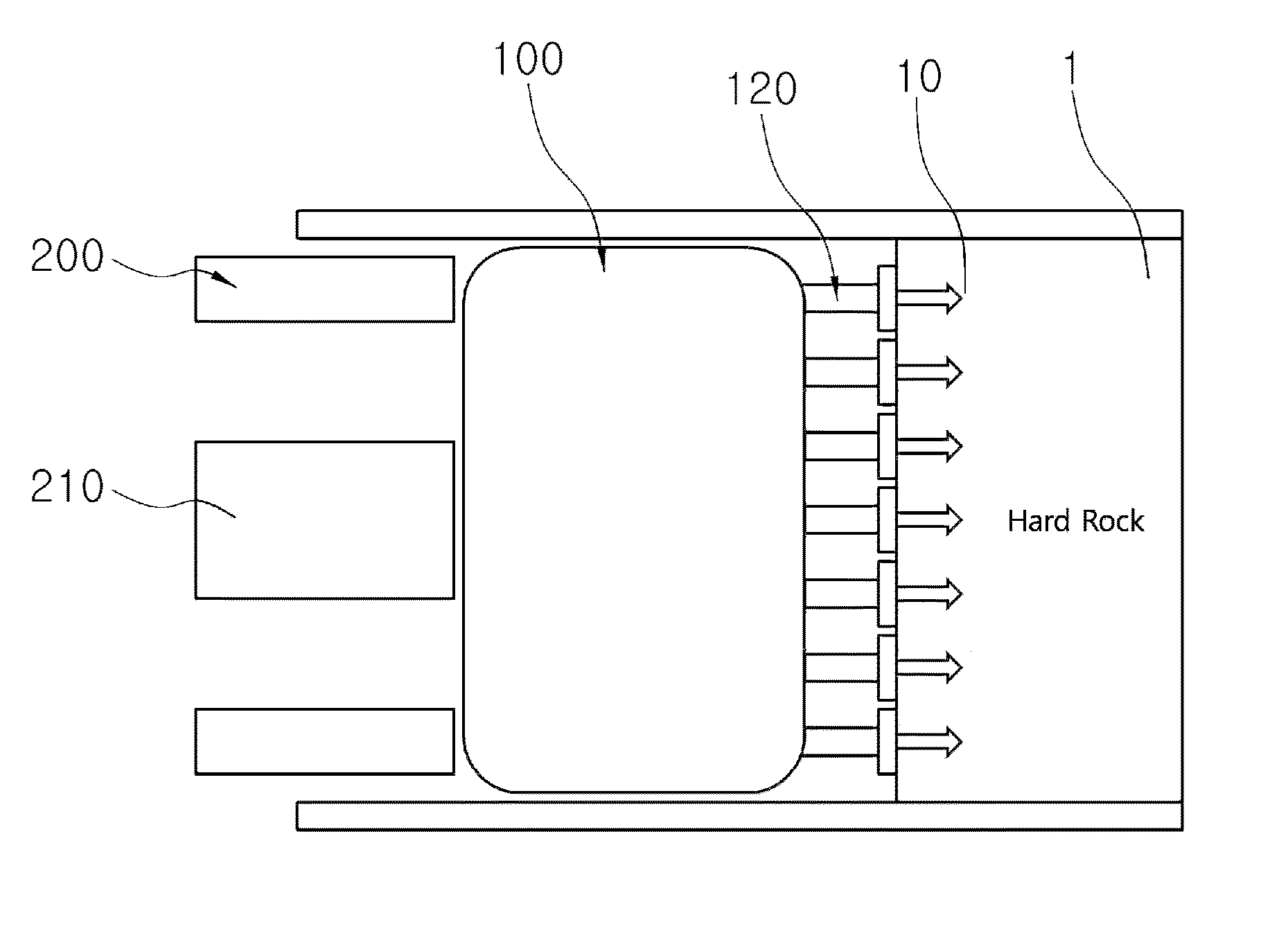
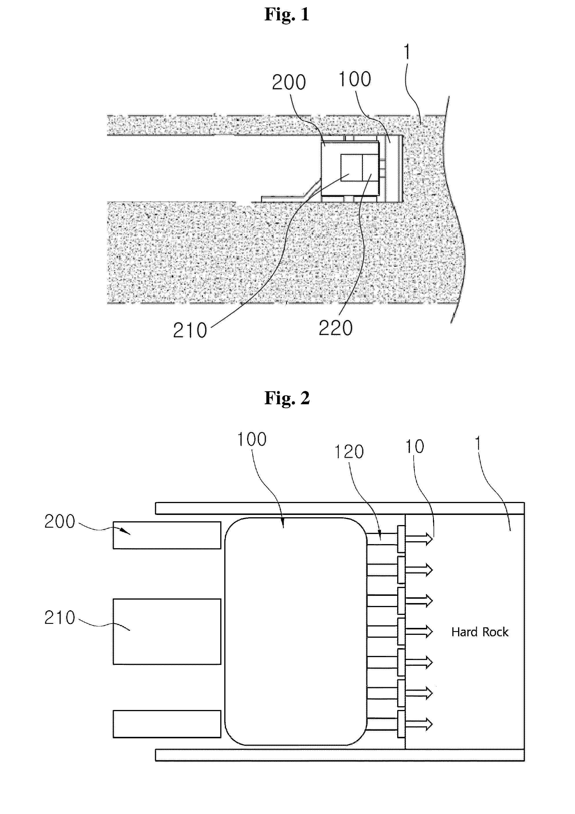
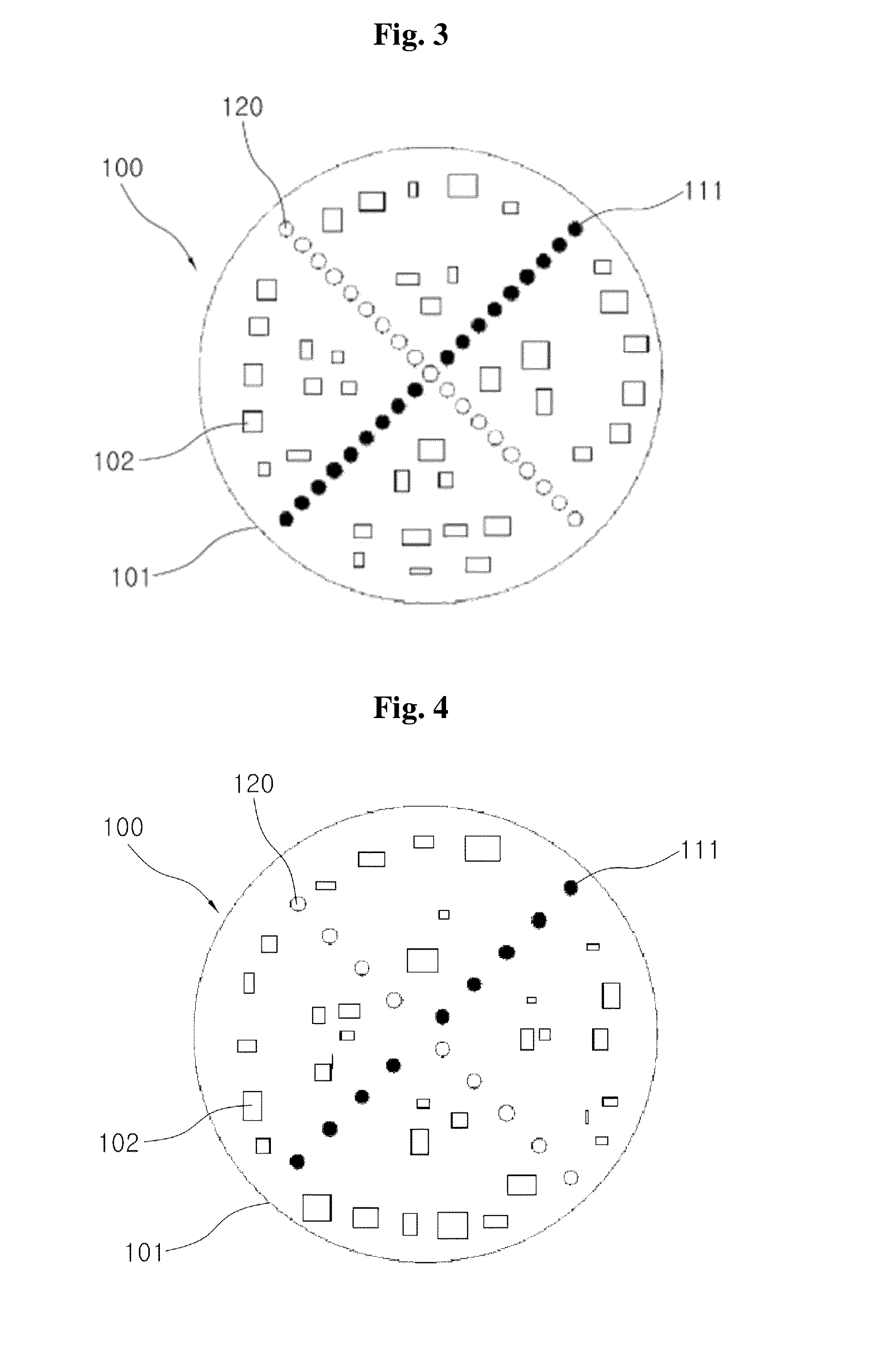
[0027]FIG. 1 illustrates an example of excavation state using a tunnel excavation device according to the present invention, FIG. 2 is a cross-sectional view of an excavation head of the tunnel excavation device according to the present invention, FIG. 3 is a front view of the excavation head of the tunnel excavation device according to the present invention, FIG. 4 is a front view of another example of the excavation head of the tunnel excavation device according to the present invention, FIG. 5 is a view illustrating an injection means constituting to the present invention and FIG. 6 is a control diagram of the tunnel excavation device according to the present invention.

[0028]Referring to FIGS. 1 to 6, the tunnel excavation device according to the present invention includes an excavation ...


PUM

PropertyMeasurementUnit
Timeaaaaaaaaaa
Shapeaaaaaaaaaa
Distanceaaaaaaaaaa

Abstract

The present invention pertains to a tunnel excavation device, which includes an excavation head, a main body on which the excavation head is rotatably mounted, a motor provided in the main body and rotates the excavation head, and a controller for controlling the motor, wherein the excavation head includes a perforating means formed by maintaining a predetermined interval from the center of a body part, which has a front surface formed in the shape of a circular plate, to the outer surface of the body part, an injection means for injecting water and liquid nitrogen into the hole formed by the perforating means, and a plurality of cutters provided on the surface of the main body for crushing the bedrock. According to the present invention, the perforating means such as a laser drill or the like forms a hole and water and liquid nitrogen are injected into the hole so as to crush the bedrock when the excavation work is carried out. Therefore, vibrations, noise and the dust may be reduced around the work site, and the progress speed of processes may be increased. In particular, the one day excavation distance becomes longer than the conventional TBM (tunnel boring machine) such that the entire tunnel construction period is reduced. Furthermore, the lifespan is elongated due to prevention of the abrasion of a cutter such that the cutter replacement time becomes longer, and the maintenance costs can be reduced.

Description

TECHNICAL FIELD[0001]The present invention relates to a tunnel excavation device, and more particularly, to a tunnel excavation device which forms holes on a bedrock through a perforating means provided on an excavation head thereof for excavating a tunnel, and injects water and liquefied nitrogen into the holes to allow the bedrock to be easily crushed using a property of water which expands upon freezing.BACKGROUND ART[0002]In general, various methods are being used in constructing a tunnel used for roads or railways. Hard bedrock is generally destructed using explosives and is excavated using excavation equipment.[0003]With the recent development of large-scale equipment called a tunnel boring machine (TBM), tunnels have been constructed without using explosives. In the TBM based tunnel construction, an excavation work is carried out on a circular cross-section, which is a mechanically stable, vibration-free, non-blasting method. Thus, the TBM based tunnel construction may be an ...

Claims


Application Information

Patent Timeline
IPC IPC(8): E21D9/10E21D9/11
CPCE21D9/1066E21D9/1073E21D9/112E21D9/0875E21D9/0879E21D9/08E21D9/087
Inventor KIM, DONG HYEON
Owner KOREA RAILROAD RES INST
Why Eureka
Try Eureka