Micro inductive sensor

a micro-inductive sensor and position sensor technology, applied in the field of position sensors, can solve the problems of inductive sensors producing greater amounts of magnetic emissions, affecting the performance of magnetic sensors, etc., and achieve the effects of reducing the size of coils, and generating more eddy curren

Inactive Publication Date: 2014-11-06
KSR IP HLDG
View PDF12 Cites 19 Cited by
  • Summary
  • Abstract
  • Description
  • Claims
  • Application Information

AI Technical Summary

Benefits of technology

[0007]In sharp contrast to conventional inductive sensors which use a metal piece as the fabricated coupler, the present invention uses a resonator as the coupler. Using a resonator as the coupler allows the transmitter coil and the coupler to become an oscillator system with a much higher quality factor (Q factor) than a conventional inductive sensor. Furthermore, the ferrite layer of the sensor package and the coupler package allows the size of the coils to be significantly reduced relative to conventional inductive sensors.
[0008]The eddy current on the coupler is the direct source of the signal on the two part receiving coil. When subjected to the same magnetic field as a conventional coupler, the resonator coupler will generate more eddy current. Therefore, using the same driving power, an inductive sensor using a resonator as the coupler can generate a much stronger electromagnetic field on the receiving coil than a conventional inductive sensor.

Problems solved by technology

Magnetic sensors can suffer performance loss as the magnet degrades and are more sensitive to magnetic disturbances from the surrounding environment.
Consequently, inductive sensors also produce greater amounts of magnetic emissions due to their larger antenna area.

Method used


Image

  • Micro inductive sensor
  • Micro inductive sensor
  • Micro inductive sensor

Examples


Embodiment Construction

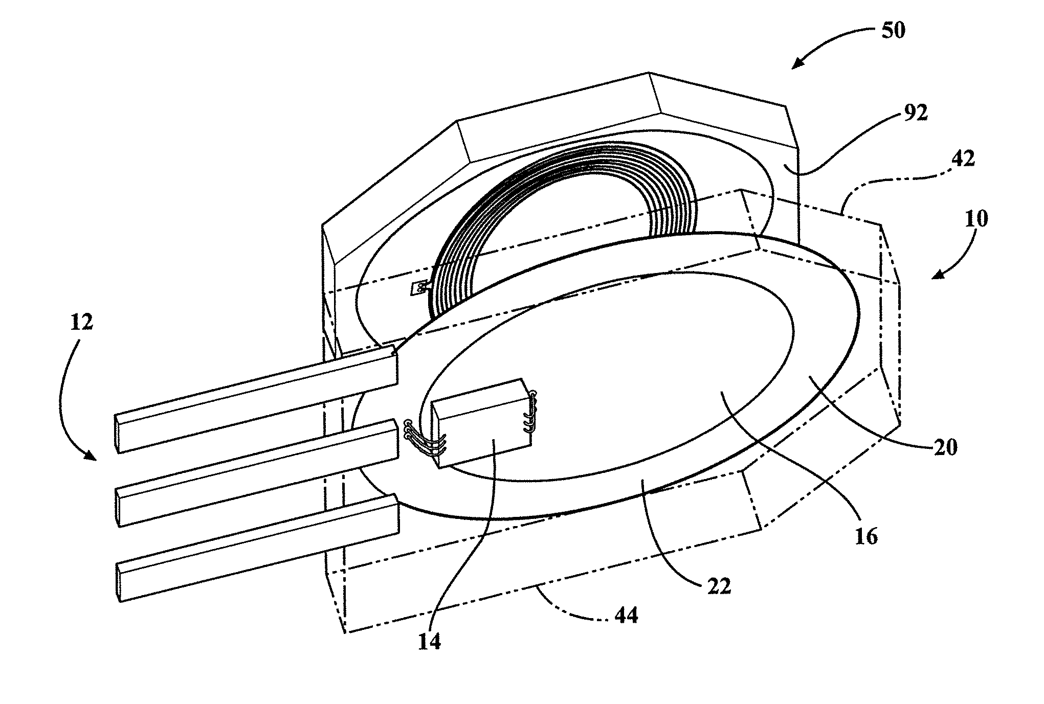
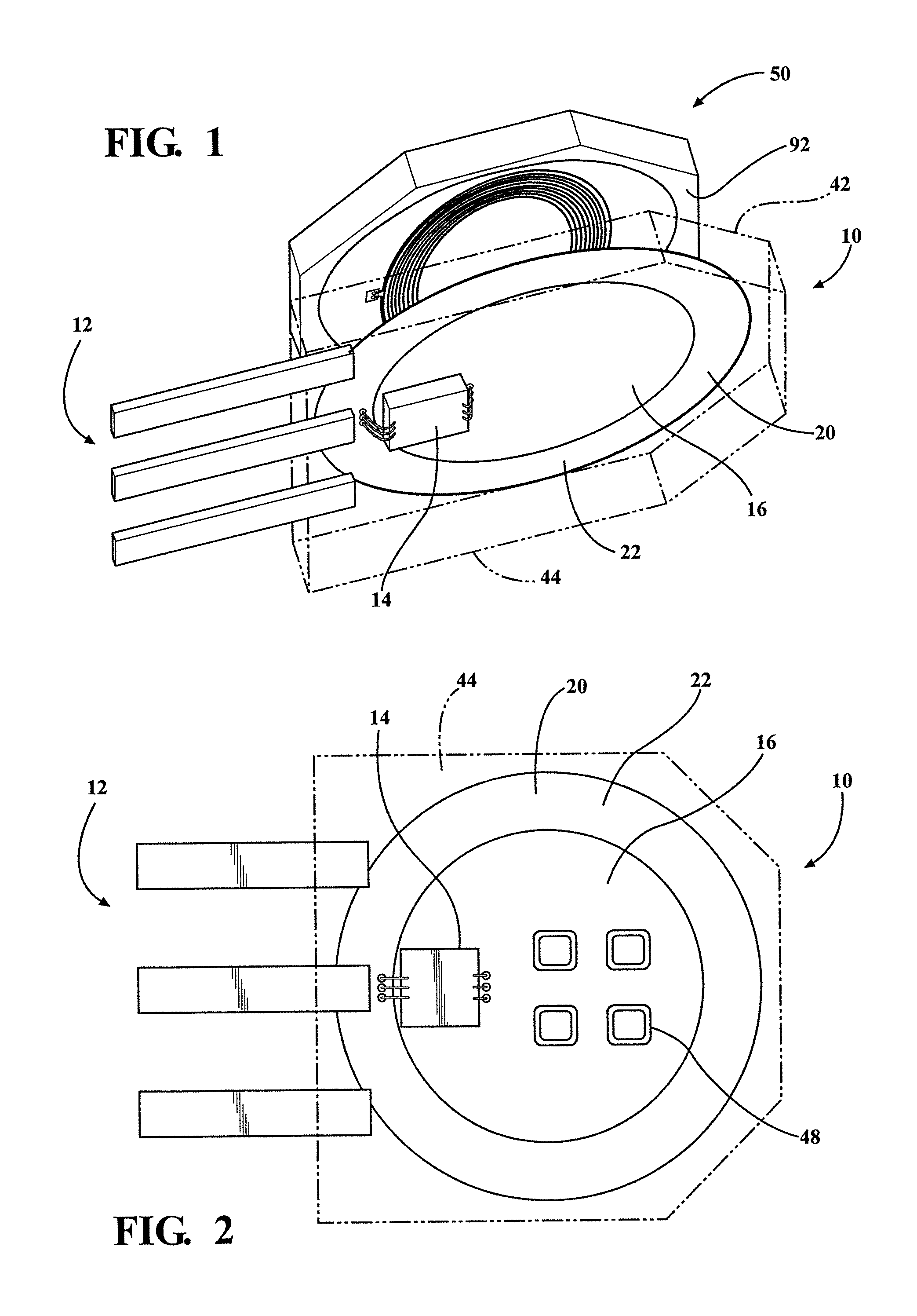
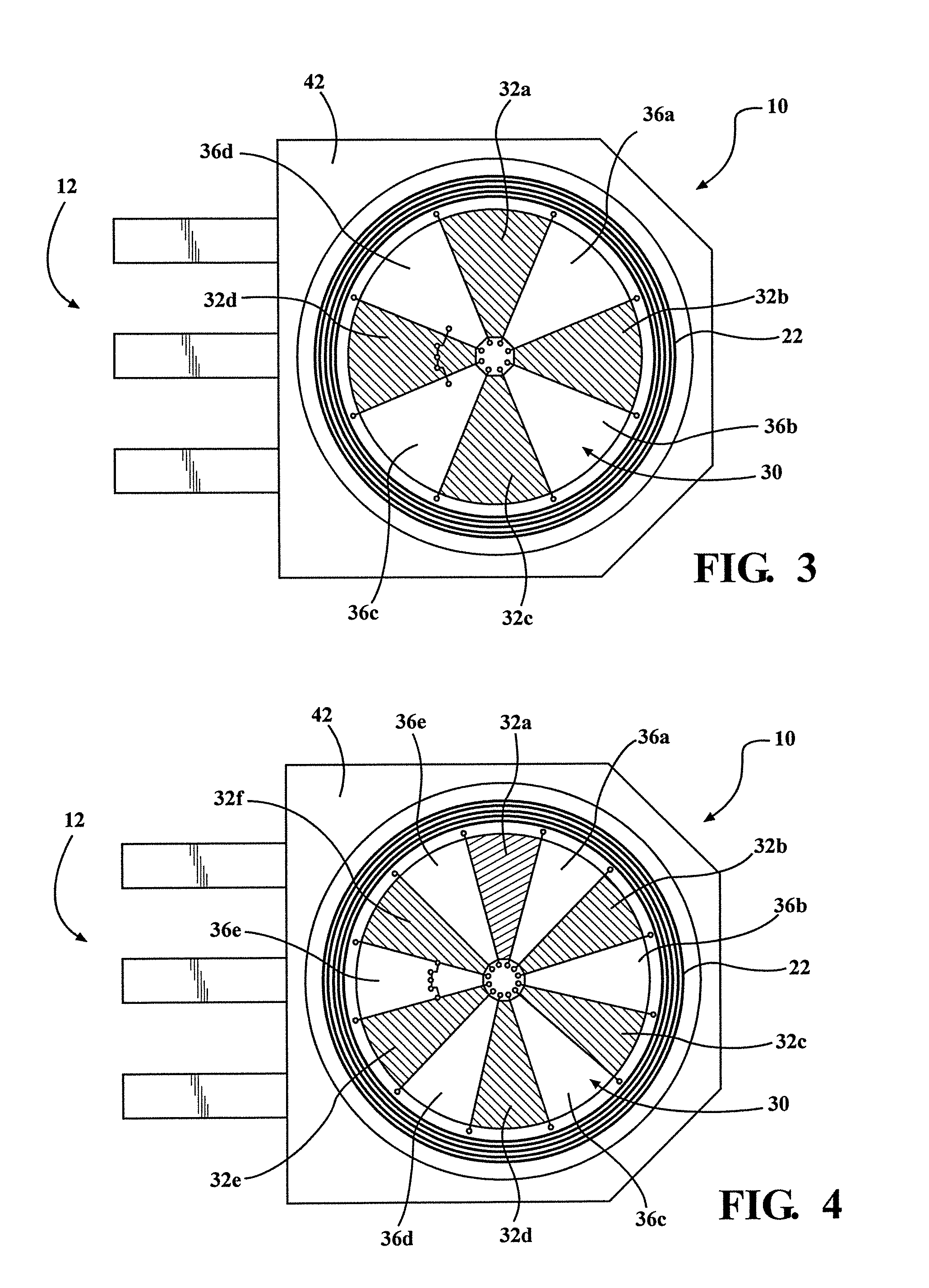
[0015]Embodiments of the present invention include a sensor package 10 and a coupler package 50. The sensor package 10 includes a plurality of pins 12, a signal processor 14, an integrated capacitor 16, a ferrite layer 20, a transmitter coil 22, a two part receiving coil 30, and a plurality of discrete components 48. The coupler package 50 includes an integrated capacitor 56, a ferrite layer 60, and a coupler coil 70. The transmitter coil 22 in the sensor package 10 is energized by an external power source (not shown) which in turn energizes the coupler coil 70 in the coupler package 50. The sensor 10 then measures the rotational position of the coupler package 50 relative to the sensor package 10 by detecting and measuring with the two part receiving coil 30 the signal returned by the coupler coil 70. The signal processor 14 calculates the position of the coupler package 50 relative to the sensor package 10 by comparing the coupling factors between the coupler package 50 and the se...


PUM


Abstract

An inductive sensor includes a sensor package and a coupler package. The sensor package includes a signal processor, an integrated capacitor, a ferrite layer, a transmitter coil, a two part receiving coil, and a plurality of discrete components. The coupler package includes an integrated capacitor, a ferrite layer, and a coupler coil. The transmitter coil in the sensor package is energized by an external power source which in turn energizes the coupler coil in the coupler package. The sensor then measures the rotational position of the coupler package relative to the sensor package by detecting and measuring, with the two part receiving coil, the signal returned by the coupler coil. The signal processor calculates the position of the coupler package relative to the sensor package by comparing the coupling factors between the coupler package and the sensor package.

Description

CROSS-REFERENCE TO RELATED APPLICATIONS[0001]This application claims priority of U.S. Provisional Application 61 / 819,118 filed May 3, 2013, the contents of which are included herein by reference.FIELD OF THE INVENTION[0002]This invention relates generally to position sensors. More particularly, this invention relates to inductive position sensors.BACKGROUND OF THE INVENTION[0003]Position sensors are often used in various mechanical control systems. Common position sensors include capacitive sensors, potentiometer sensors, and magnetic position sensors. However, inductive sensors are one of the most commonly used position sensors in vehicles. Inductive sensors detect the position of a target by measuring the mutual inductance between the target and the sensing coil. Compared to other magnetic position sensors, inductive sensors are more cost effective because they do not need a magnet and instead use an electromagnetic coil.[0004]Inductive sensors are also desirable to use in vehicle...

Claims


Application Information

Patent Timeline
Patent Type & Authority Applications(United States)
IPC IPC(8): G01D5/20
CPCG01D5/204
Inventor ELLIOTT, RYAN W.SHAO, LINGMIN
Owner KSR IP HLDG
Why Eureka
Try Eureka