Airfoil with cooling passages

a technology of airfoil and cooling passage, which is applied in the field of airfoil, can solve the problems of difficult cooling effective, difficult to meet the mechanical stress of operation, so as to improve the cooling concept efficiency of the blade or the airfoil improve the thermal efficiency of the gas turbine, and reduce the secondary air consumption

Inactive Publication Date: 2014-11-06
SIEMENS AG
View PDF15 Cites 20 Cited by
  • Summary
  • Abstract
  • Description
  • Claims
  • Application Information

AI Technical Summary

Benefits of technology

[0006]Considering the problems and challenges of the prior art it is one object of the invention to improve the cooling concept efficiency of a gas turbine's blade or vane airfoil. The invention especially focuses on the trailing edge of said airfoil. It is a further object to improve the thermal efficiency of a gas turbine by reducing the secondary air consumption.

Problems solved by technology

Modern gas turbines operate at combustion temperatures of approximately 1300° C. which thermal impact makes it currently nearly impossible for any material to be suitable for the mechanical stress of operation and to be suitable to fulfill lifetime requirements without additional measures to extend lifetime.
This technical task becomes most challenging in the case of a first stage gas turbine blade and a first stage gas turbine vane.
The trailing edge of a gas turbine vane airfoil or a rotor blade airfoil is a region that is very difficult to cool effectively for several reasons.
The so called secondary air consumption has a significant impact on the efficiency of a gas turbine since the secondary air mixing with the hot gas from the combustor cools down the hot gas temperature and therefore reduces the Carnot-efficiency as well as the overall thermal efficiency of this Brayton cycle.

Method used


Image

  • Airfoil with cooling passages
  • Airfoil with cooling passages
  • Airfoil with cooling passages

Examples


Embodiment Construction

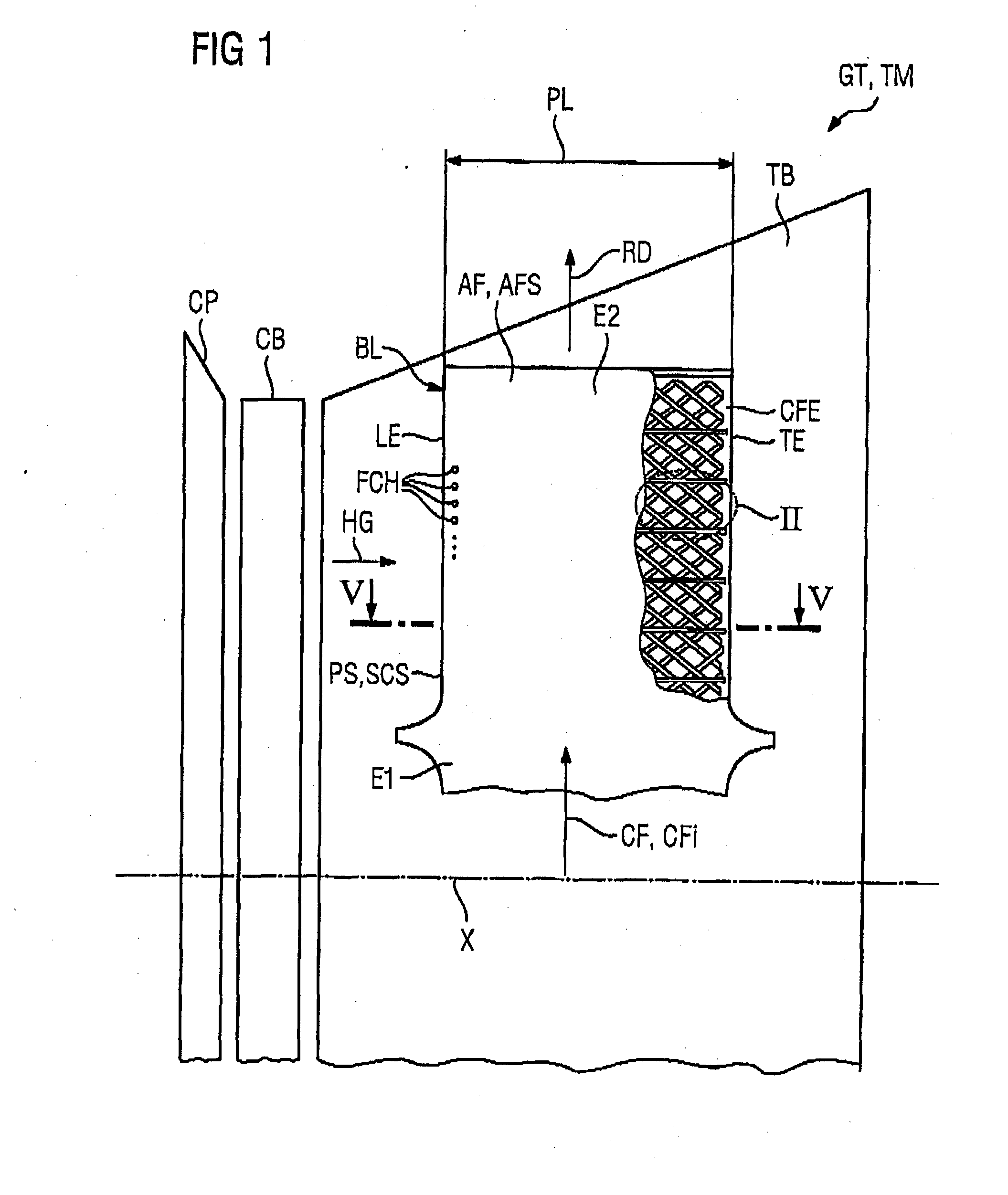
[0021]FIG. 1 shows an airfoil AF according to the invention schematically.

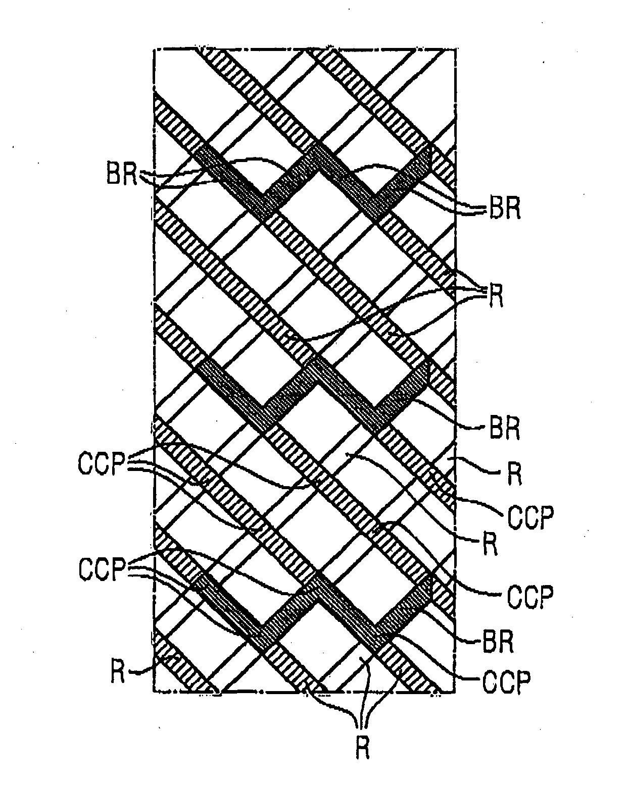
[0022]Further FIG. 1 shows—simplified—a turbo machine TM, respectively a gas turbine GT comprising a compressor CP a combustor CB and a turbine TB, all of which are schematically indicated in FIG. 1. Also indicated is a rotor axis X extending perpendicular to a radial direction RD, which coincides with a lengthwise direction of said airfoil AF. The airfoil AF of a blade BL for said turbo machine TM respectively said gas turbine GT comprises a leading edge LE and a trailing edge TE, wherein the leading edge is the most upstream part of the airfoil AF with regard to a stream of hot gas HG generated by said combustor CB and flowing along the airfoils surface AFS. The airfoil AF extends from a first end E1 to a second end E2 and a cooling fluid CF enters an inner cavity of the airfoil AF through a cooling fluid inlet CFI at said first end E1. While a part of the cooling fluid CF is ejected into the hot gas HG thro...


PUM


Abstract

An airfoil having cooling passages inside is provided, wherein each radial cross section of the airfoil has a shape of specific profile, wherein hot gas flows along the airfoil's surface from a leading edge to trailing edge, the airfoil's surface comprises a pressure-side and suction-side defined by the trailing edge and leading edge, wherein the trailing edge has cooling fluid discharge exits, the pressure-side and suction-side are respectively defined by a wall comprising an inner surface and an outer surface, which inner surface has ribs extending in a rib-direction inclined to the radial direction, wherein along a portion of at least 10% of the profile's lengths the inclined ribs contact each other at respective cross-contact-points, forming a 2-dimensional matrix. At least one additional blocking-rib extends from the pressure-side to the suction-side and extends from one cross-contact-point to another to cause additional turbulence of said cooling fluid flow to be discharged.

Description

CROSS REFERENCE TO RELATED APPLICATIONS[0001]This application is the US National Stage of International Application No. PCT / RU2011 / 000928 filed Nov. 25, 2011, and claims the benefit thereof, and is incorporated by reference herein in its entirety.FIELD OF INVENTION[0002]The invention relates to an airfoil of a blade or a vane for a turbo machine, especially a gas turbine, wherein cooling passages are provided inside said airfoil, wherein said airfoil extends in a radial direction from a first end to a second end, wherein a cooling fluid inlet is provided at said first end or said second end, wherein each radial cross section of said airfoil has a shape of a specific profile, wherein said airfoil is made to be exposed to a hot gas flowing along said airfoil's surface from a leading edge to a trailing edge of said profile, wherein said airfoil's surface comprises a pressure-side and a suction-side which are defined from each other by said trailing edge and said leading edge, wherein s...

Claims


Application Information

Patent Timeline
Patent Type & Authority Applications(United States)
IPC IPC(8): F01D5/18
CPCF01D5/186F05D2260/202F05D2260/201F01D5/187F02C7/18F05D2260/2212F05D2260/22141F05D2250/314
Inventor BREGMAN, VITALYSEMENOV, ALEXANDERUTRIAINEN, ESA
Owner SIEMENS AG
Why Eureka
Try Eureka