Container for the laboratory area and method for marking such a container
a technology for laboratory containers and containers, applied in the field of laboratory containers, can solve the problems of high production cost, complex cuvette production, and damage to the outer layer, and achieve the effect of simple and inexpensive production, detection reliably and well, and simple and inexpensive production
- Summary
- Abstract
- Description
- Claims
- Application Information
AI Technical Summary
Benefits of technology
Problems solved by technology
Method used
Image

Examples
first embodiment
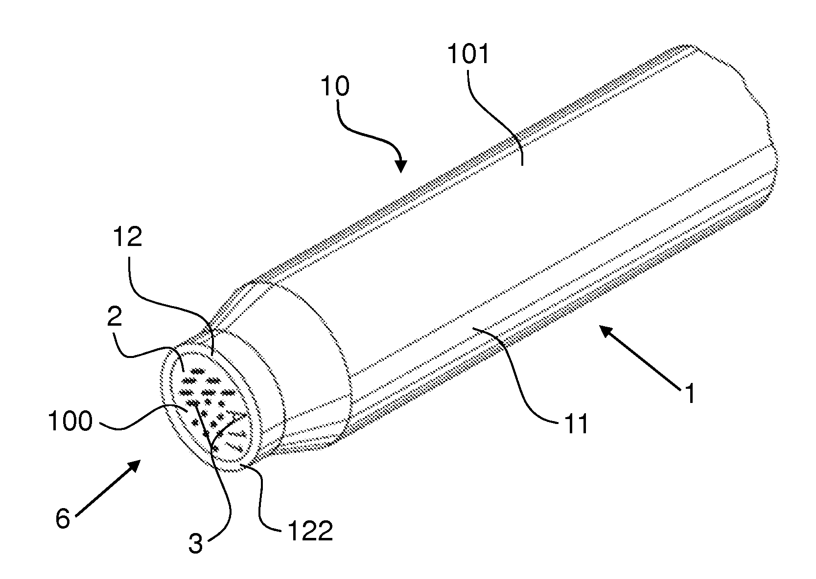
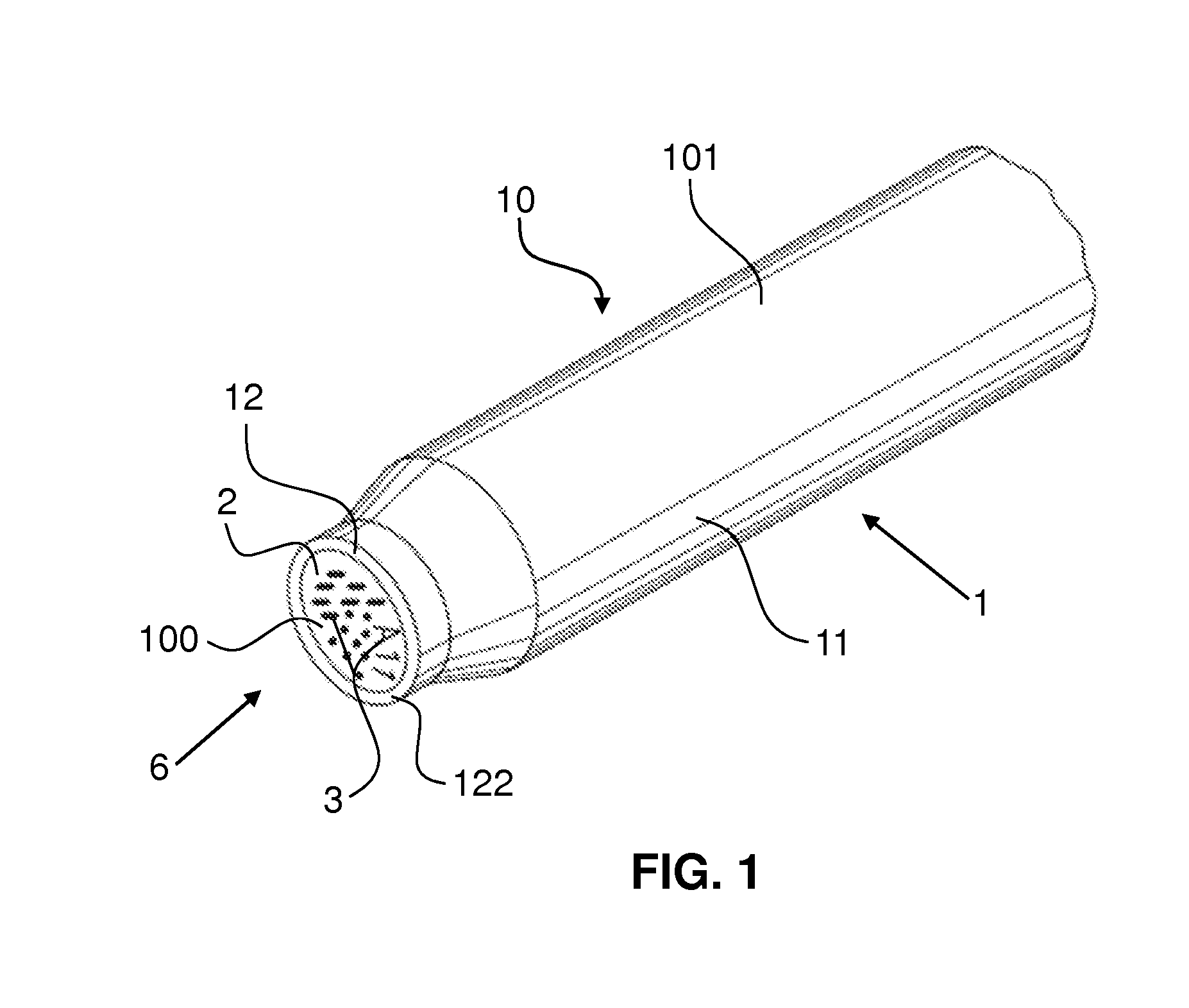
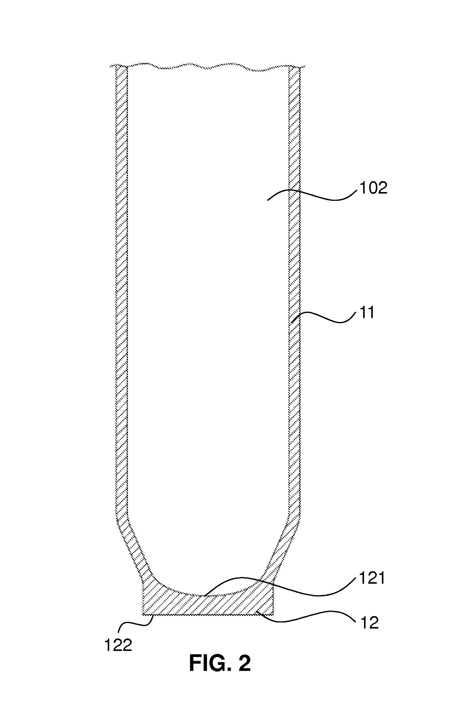
[0072]FIG. 3 schematically shows a lateral, central sectional view of the lower region of a container 10 according to the invention, which is formed as a cuvette and has an indicated, upwardly open cavity 102. The cuvette has the body 1 in the form of a cuvette, which is formed in a way corresponding to that shown in FIG. 2. In the bottom 12 of the body 1 there are local material modifications 3, which in the case of this embodiment are in the interior of the body 1. On the bottom surface 122 of the body 1, an opaque layer 2 is provided by means of a transparent bonding layer 5, such as for example an adhesive. The bonding layer 5 covers the entire bottom surface 122 of the body 1. The opaque layer 2 has in the region of the material modifications 3 clearances 21, through which the material modifications 3 can be seen from the outside. In the case of the embodiment represented here, the material modifications 3 are not only present in the region exposed by the clearances 21, but pro...
third embodiment
[0074]FIG. 5 schematically shows a lateral, central sectional view of the lower region of a container 10 according to the invention, which is formed as a cuvette. The body 1 has in the bottom 12 local material modifications 3, which in this embodiment are located on the surface of the body 1, but recessed in the bottom 12. On the bottom surface 122 of the body 1, an opaque layer 2 is arranged directly on it. The opaque layer 2 has in the region of the material modifications 3 clearances 21, which are formed as rectilinearly extending cylinders and through which the material modifications 3 can be seen from the outside. In the case of the embodiment according to FIG. 5, the material of the body 1 may be transparent or opaque, since the clearances 21 extend as far as the material modifications 3.
[0075]The clearances 21 are formed as a circular area in cross section in the region of the surface of the opaque layer 2 that forms the bottom surface 100 of the container 10 and have a diame...
sixth embodiment
[0078]FIG. 8 schematically shows a lateral, central sectional view of the lower region of a container 10 according to the invention, which is formed as a cuvette. As a difference from the embodiment represented in FIG. 6, in this embodiment the material modifications 3 represent a change in colour of particles embedded in the body 1, the particles being pigments for example, and it being possible for the change in colour to be brought about for example by the irradiation of the particles with a laser beam. In the case of this embodiment, the opaque layer 2 forms the bottom surface 100 of the container 10. The material of the body 1 is transparent, in order that the optical reader can detect the material modifications 3.
PUM
| Property | Measurement | Unit |
|---|---|---|
| wavelength range | aaaaa | aaaaa |
| wavelength range | aaaaa | aaaaa |
| height | aaaaa | aaaaa |
Abstract
Description
Claims
Application Information
 - R&D
- Intellectual Property
- Life Sciences
- Materials
- Tech Scout
- Unparalleled Data Quality
- Higher Quality Content
- 60% Fewer Hallucinations
Browse by: Latest US Patents, China's latest patents, Technical Efficacy Thesaurus, Application Domain, Technology Topic, Popular Technical Reports.
© 2025 PatSnap. All rights reserved.Legal|Privacy policy|Modern Slavery Act Transparency Statement|Sitemap|About US| Contact US: help@patsnap.com