Control pedal and method of controlling an electronic device with the control pedal

a technology of electronic devices and control pedals, applied in the field of control pedals, can solve the problems of affecting performance, inconvenient carrying along with the musician, and inconvenience for the musician to manually turn the pages, and achieve the effect of preventing its displacemen

Inactive Publication Date: 2014-11-13
CHO CHIOU JI
View PDF19 Cites 21 Cited by
  • Summary
  • Abstract
  • Description
  • Claims
  • Application Information

AI Technical Summary

Benefits of technology

[0028]According to other embodiments of the present invention, in order, an anti-slip pad may also be arranged at a bottom of the control pedal to prevent its displacement when a touch action is applied thereon.

Problems solved by technology

However, it may be inconvenient for the musician to manually turn the pages of the sheet music and play an instrument at the same time: for example, the sheet music may be turned to a wrong page, which may affect the performance.
Moreover, the sheet music is usually in paper form, which is inconvenient to carry along with the musician.
Unfortunately, the use of the electronic device still requires manual operation to turn the pages of the sheet music displayed on the electronic device.
However, the above page turning control requires the assembly of the left and right pedals 31 and 32 and the wireless transmitter 33, which increase the overall volume and total weight and inconvenient to carry.
Because the operator needs to use one or two feet to press on one or two of the pedals 31 and 32, the actuation may also be cumbersome.
More importantly, pressing on the pedal may result in undesirable noises, and a prolonged use of the pedal may also generate parasitic noise induced by mechanical friction, which may adversely affect the quality of the performance.
Playing the instrument and performing manual adjustment at the same time is not an easy task and may lead to confusion, which finally may affect the performance.

Method used


Image

  • Control pedal and method of controlling an electronic device with the control pedal
  • Control pedal and method of controlling an electronic device with the control pedal
  • Control pedal and method of controlling an electronic device with the control pedal

Examples


second embodiment

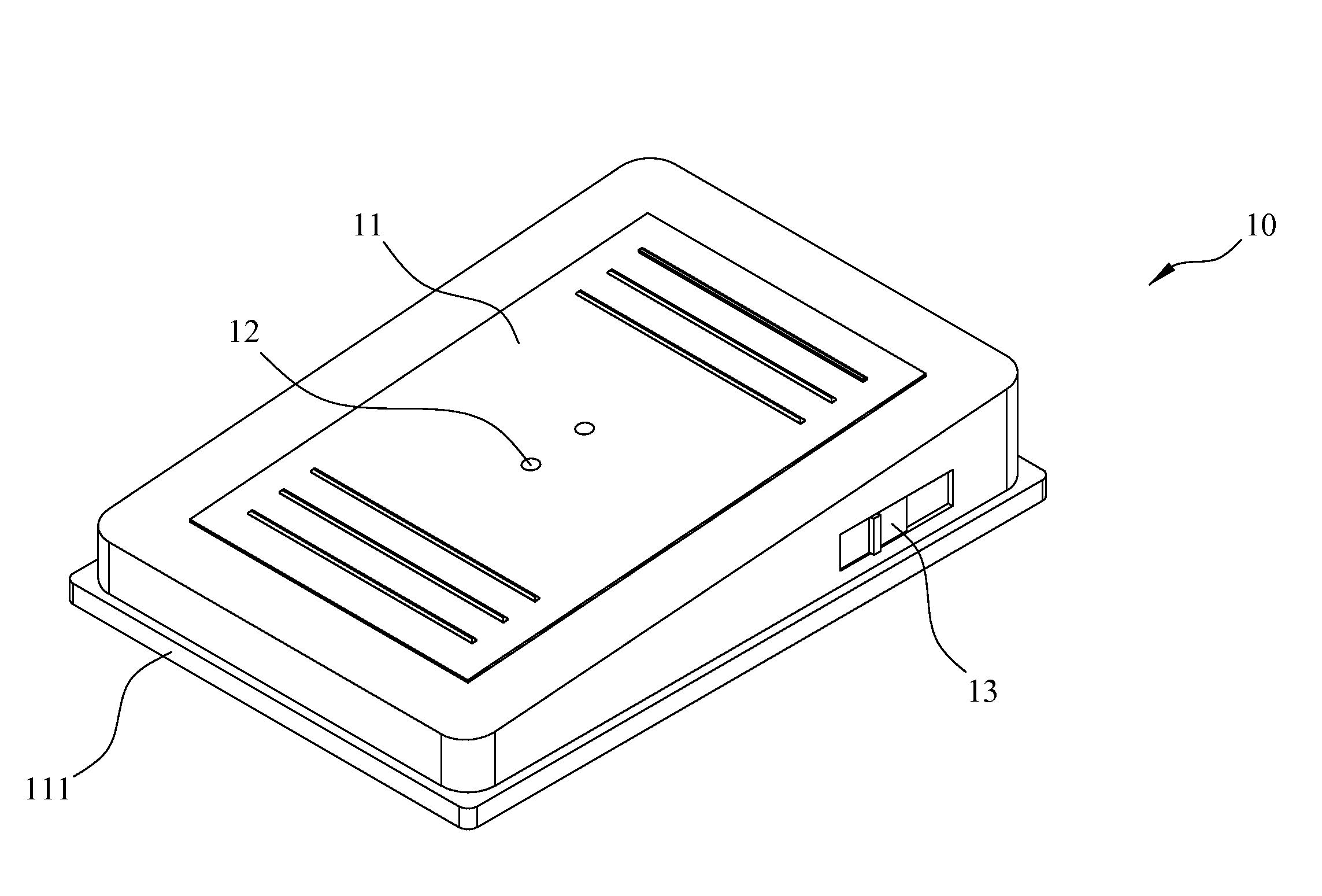
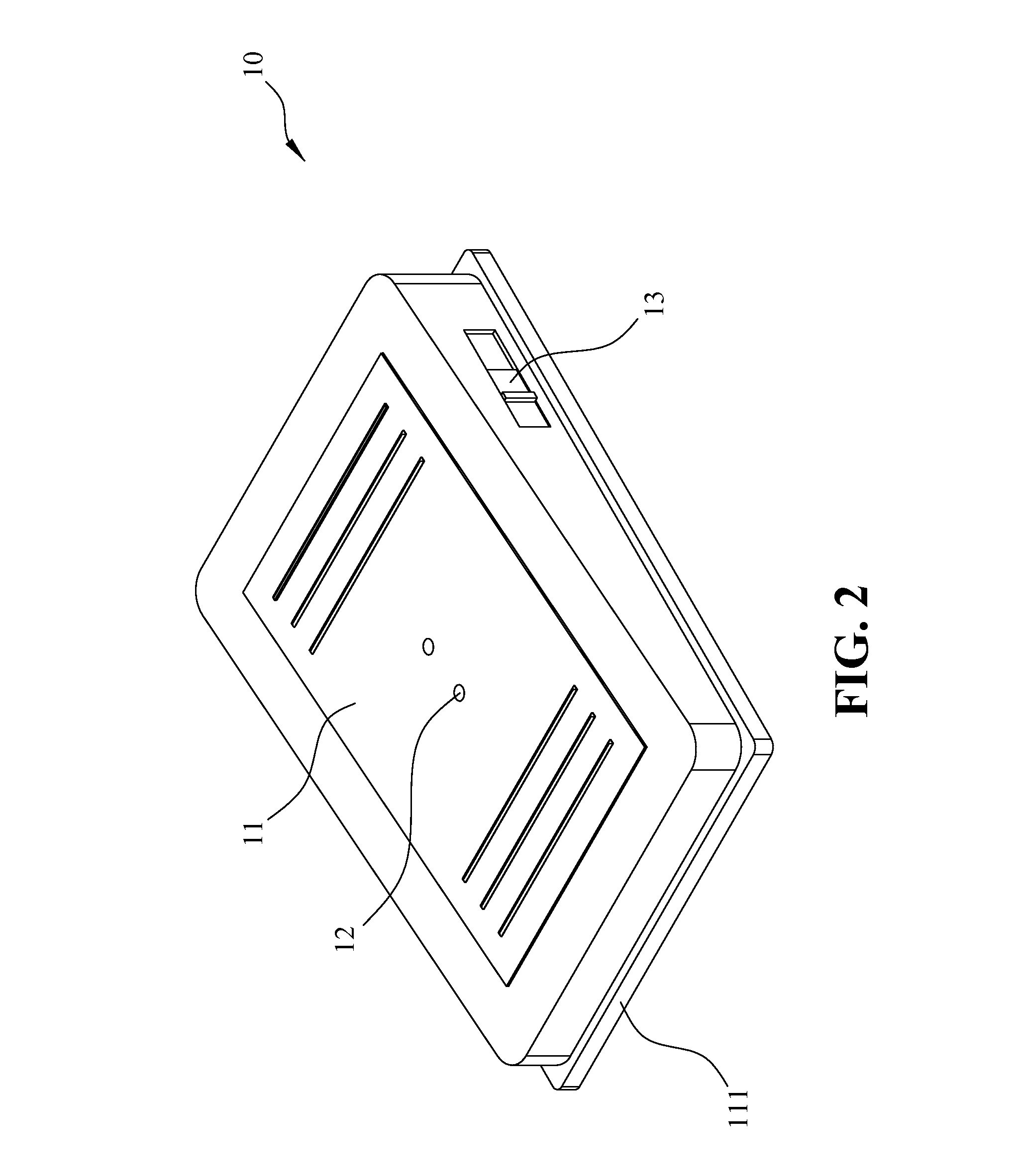
[0043]FIG. 4 is a block diagram illustrating a control pedal 10 according to the present invention. The contact surface 111 of the control pedal 10 also has a sensing unit 12 that senses and detects the application of the touch action 121 by a user's foot, and then generates the sensor signal 122. The sensor signal 122 is then transmitted to the microprocessor 14, which reads the sensor signal 122 and generates a page turning instruction 142. The page turning instruction 142 is transmitted via the wireless transmission unit 151 to a display device 21 so as to execute a page turning action on the display device 21. The display device 21 preferably includes a receiving interface, which in fact is a wire receiving interface, or a wireless receiving interface such as Bluetooth or infrared unit. The display device 21 is a laptop computer, a desktop computer, a tablet computer, a projector device, and the like.

[0044]Examples of the touch action 121 include, without limitation, a single to...

third embodiment

[0046]FIG. 5 is a block diagram illustrating a control pedal 10 according to the present invention. The contact surface 111 of the control pedal 10 also has a sensing unit 12 that senses and detects the application of the touch action 121 by a user's foot, and then generates the sensor signal 122. The sensor signal 122 is then transmitted to the microprocessor 14, which reads the sensor signal 122 and generates a volume control instruction 143 for sound. The volume control instruction 143 is transmitted via the wireless transmission unit 151 to an electronic music instrument 22 so as to perform sound volume control. The electronic music instrument 22 preferably includes a receiving interface, which in fact is a wire receiving interface, or a wireless receiving interface such as Bluetooth or infrared unit. Examples of the electronic music instrument 22 include, without limitation, an electronic guitar, electronic bass, a keyboard, MIDI, DJ amplifier, and the like.

[0047]Examples of th...

fourth embodiment

[0048]FIG. 6 is a block diagram illustrating a control pedal 10 according to the present invention. The contact surface 111 of the control pedal 10 also has a sensing unit 12 that senses and detects the application of the touch action 121 by a user's foot, and then generates the sensor signal 122. The sensor signal 122 is then transmitted to the microprocessor 14, which reads the sensor signal 122 and generates an audio mode switch instruction 144. The audio mode switch instruction 144 is transmitted via the wireless transmission unit 151 to an electronic music instrument 22 so as to switch an audio mode. The electronic music instrument 22 preferably includes a receiving interface, which in fact is a wire receiving interface, or a wireless receiving interface such as Bluetooth or infrared unit. Examples of the electronic music instrument 22 preferably includes, without limitation, an electronic guitar, an electronic bass, and the like.

[0049]Examples of the touch action 121 may inclu...


PUM


Abstract

A control pedal includes a pedal body having a foot contact surface at an upper side; at least a sensing unit arranged on the foot contact surface for detecting a touch action and generating a sensor signal according to the detected touch action; a microprocessor arranged in an interior of the pedal body for generating an operation instruction according to the sensor signal; and a transmission unit for transmitting the operation instruction to an electronic device to control a page turning action, sound volume adjustment, or audio mode switch.

Description

CROSS-REFERENCES TO RELATED APPLICATIONS[0001]This application claims the priority of Taiwanese patent application No. 102116543, filed on May 9, 2013, which is incorporated herewith by reference.BACKGROUND OF THE INVENTION[0002]1. Field of the Invention[0003]The present invention relates to a control pedal for controlling the execution of a transmission signal so as to perform a corresponding task in an electronic device.[0004]2. The Prior Arts[0005]A musician generally uses sheet music during a performance. However, it may be inconvenient for the musician to manually turn the pages of the sheet music and play an instrument at the same time: for example, the sheet music may be turned to a wrong page, which may affect the performance. Moreover, the sheet music is usually in paper form, which is inconvenient to carry along with the musician.[0006]One approach to solve the aforementioned issue is to input the sheet music and notation in an electronic device, and a press button may be ...

Claims


Application Information

Patent Timeline
Patent Type & Authority Applications(United States)
IPC IPC(8): G10G1/00G10H1/46G10H1/00
CPCG10G1/00G10H1/0008G10H1/46B42D9/04G10G7/00G10H1/18G10H1/346G10H1/386G10H2220/415G10H2220/435G10H2240/321
Inventor CHO, CHIOU-JI
Owner CHO CHIOU JI
Why Eureka
Try Eureka