Method and system for positioning an apparatus for monitoring a parabolic reflector aerially
- Summary
- Abstract
- Description
- Claims
- Application Information
AI Technical Summary
Benefits of technology
Problems solved by technology
Method used
Image

Examples
example
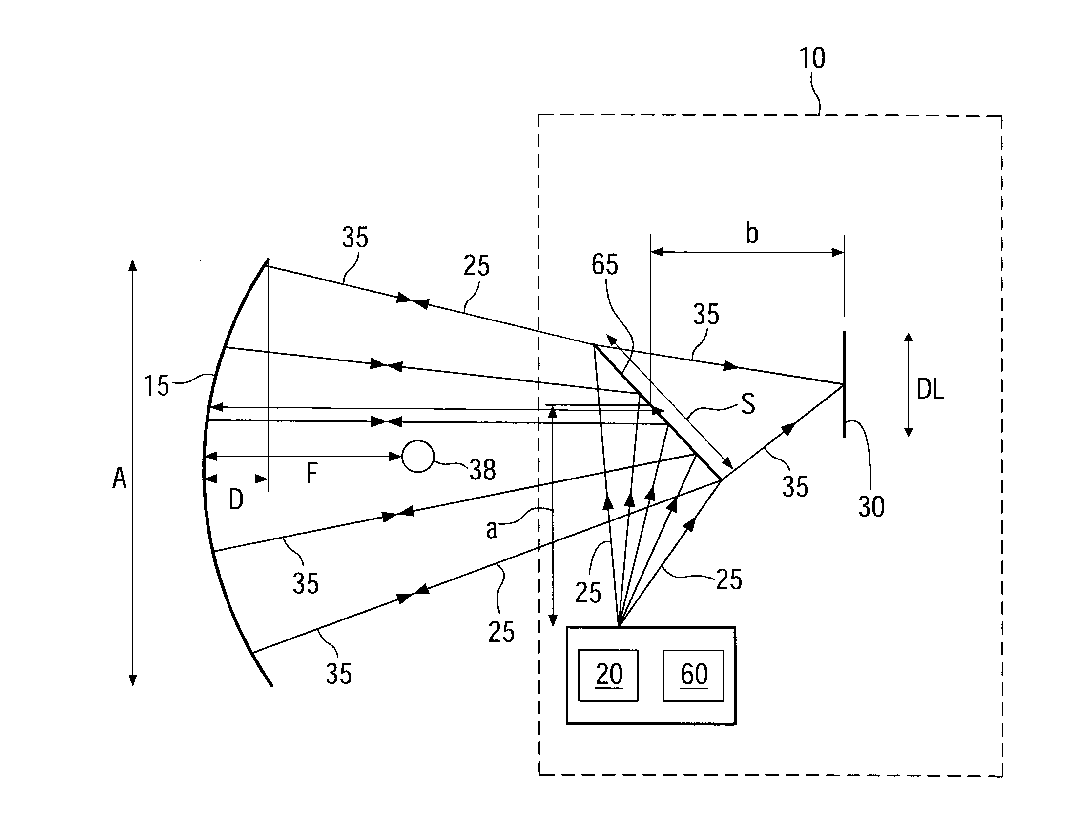
[0081]With reference to FIG. 12, an example of calculation of dimensions and positions of the components of the apparatus 10 of FIGS. 1 to 5 is provided.
[0082]FIG. 12 with reference to FIG. 4 illustrates a schematic diagram of an apparatus 10. In the illustrated example of FIG. 12, the length A of the aperture of the parabolic reflector 15 is 5.77 m. The length L of FIG. 9 of the parabolic reflector 15 is 4 m. The focal length F is 1.71 m and the depth D of the parabolic reflector 15 is 1.21 m. The diameter d of the absorber tube 38 is 50 mm and the distance C from the parabolic reflector 15 to the center of curvature is 3.42 m. The length S of the beam slitter 65 is 50 mm and the length DL of the detector is 30 mm. The distance a between the beam splitter 65 and the light source 20 is 15 mm and the distance b between the detector 30 and the beam splitter 65 is 15 mm. Referring to the sizes and dimensions of the components of the apparatus 10 and the distances between the components...
PUM
 Abstract
Description
Claims
Application Information
 - Generate Ideas
- Intellectual Property
- Life Sciences
- Materials
- Tech Scout
- Unparalleled Data Quality
- Higher Quality Content
- 60% Fewer Hallucinations
Browse by: Latest US Patents, China's latest patents, Technical Efficacy Thesaurus, Application Domain, Technology Topic, Popular Technical Reports.
© 2025 PatSnap. All rights reserved.Legal|Privacy policy|Modern Slavery Act Transparency Statement|Sitemap|About US| Contact US: help@patsnap.com