Tunable clock distribution system

a clock distribution and clock technology, applied in the direction of generating/distributing signals, pulse techniques, instruments, etc., can solve the problem of large variability, and achieve the effect of improving the test process, minimizing clock skew, and increasing the potential skew

Active Publication Date: 2014-11-13
COOKE LAURENCE H
View PDF8 Cites 4 Cited by
  • Summary
  • Abstract
  • Description
  • Claims
  • Application Information

AI Technical Summary

Benefits of technology

[0008]In another embodiment, if the contents of each flip-flop may be propagated and subsequently captured on successive clocks in a manner similar to U.S. Pat. No. 5,130,568 granted Jul. 14, 1992 to Miller et al., then case-specific tests with propagation through combinatorial logic paths to one or more internal flip-flops may be run on the IC, repeatedly increasing the clock frequency until failures occur. The shortest clock period may then be assigned to each failing combinatorial logic path. Using the delays for these combinatorial logic paths, the clock frequency may be determined, and the residual delays may be programmed into the tunable clock distribution structure. While Miller's flip-flop may improve the test process by eliminating the need for repeated testing, it may require separating the master and slave clocks, thereby increasing the potential skew between them.
[0009]Therefore, another embodiment of the present invention may include an improved scan flip-flop, which may propagate and capture data on successive clock cycles and may use the same system clock signals for both the master and slave latches to minimize clock skew.

Problems solved by technology

Still, for high speed designs, where the critical logic paths consist of 5 or fewer levels of logic, each with short segments and limited fan-out, the variation may be quite large.

Method used


Image

  • Tunable clock distribution system
  • Tunable clock distribution system
  • Tunable clock distribution system

Examples


Embodiment Construction

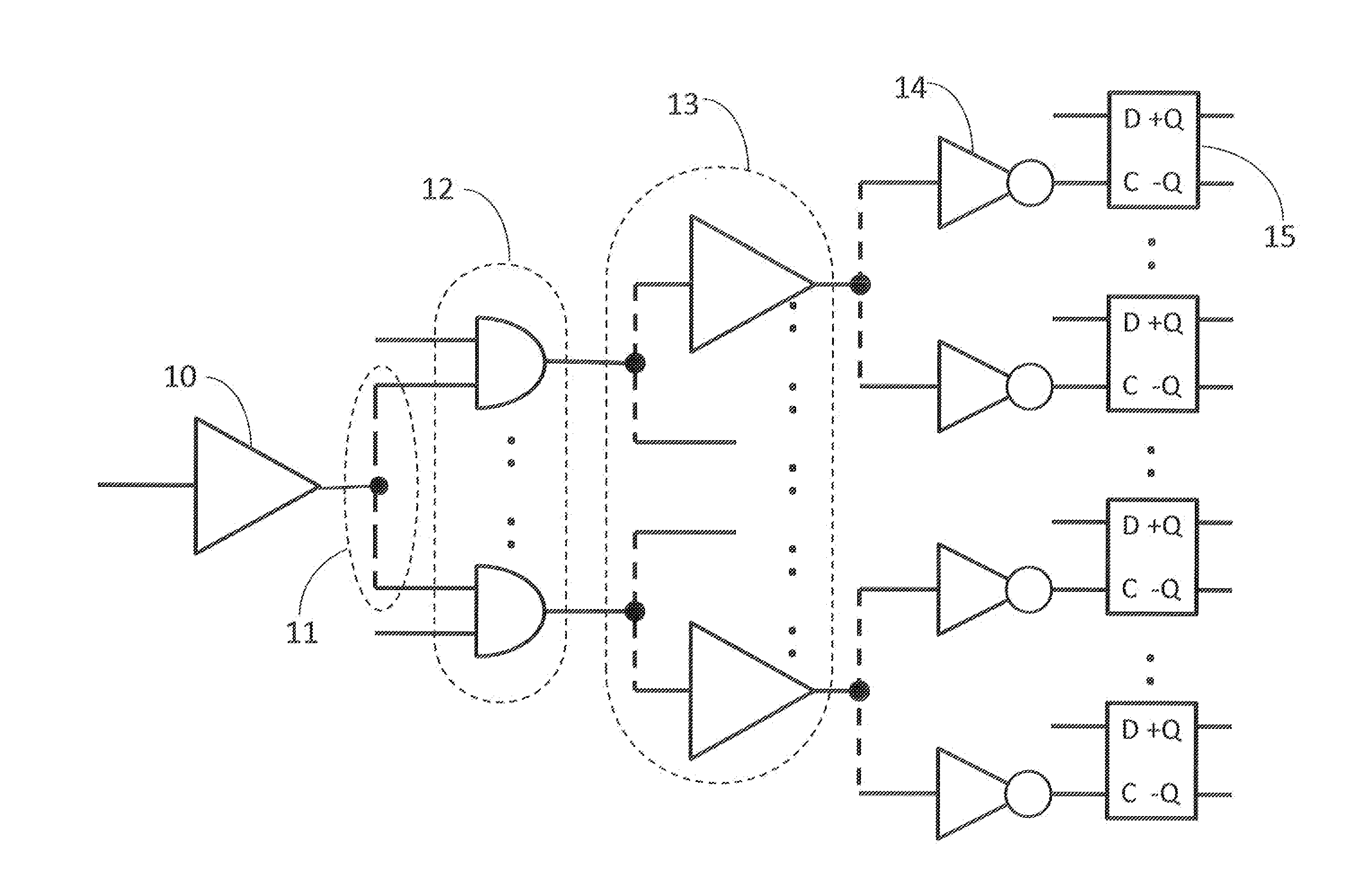
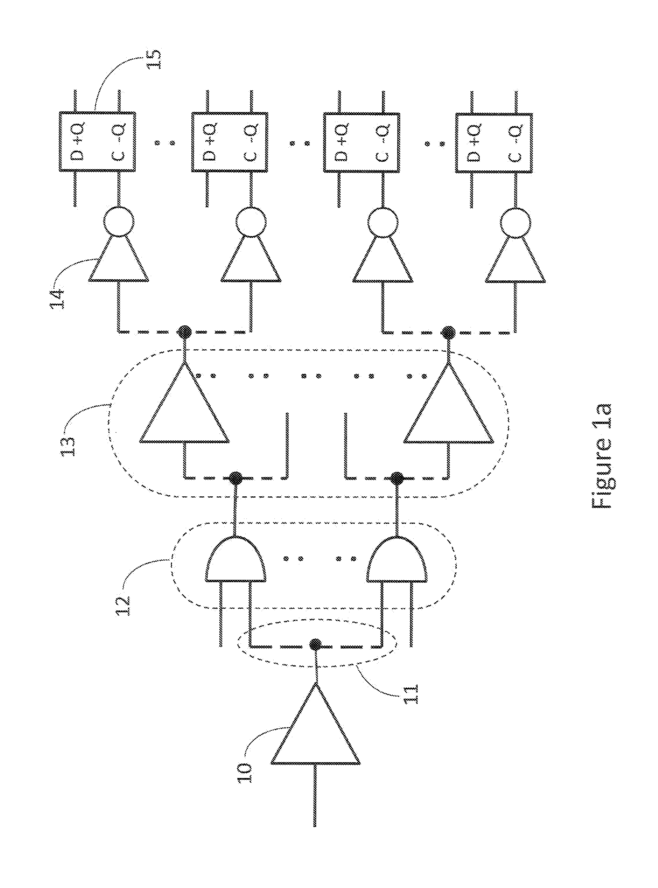
[0004]Various embodiments of the invention may relate to clock distribution structures using antifuse or phase change memory elements and methods for tuning the clock distribution structures.

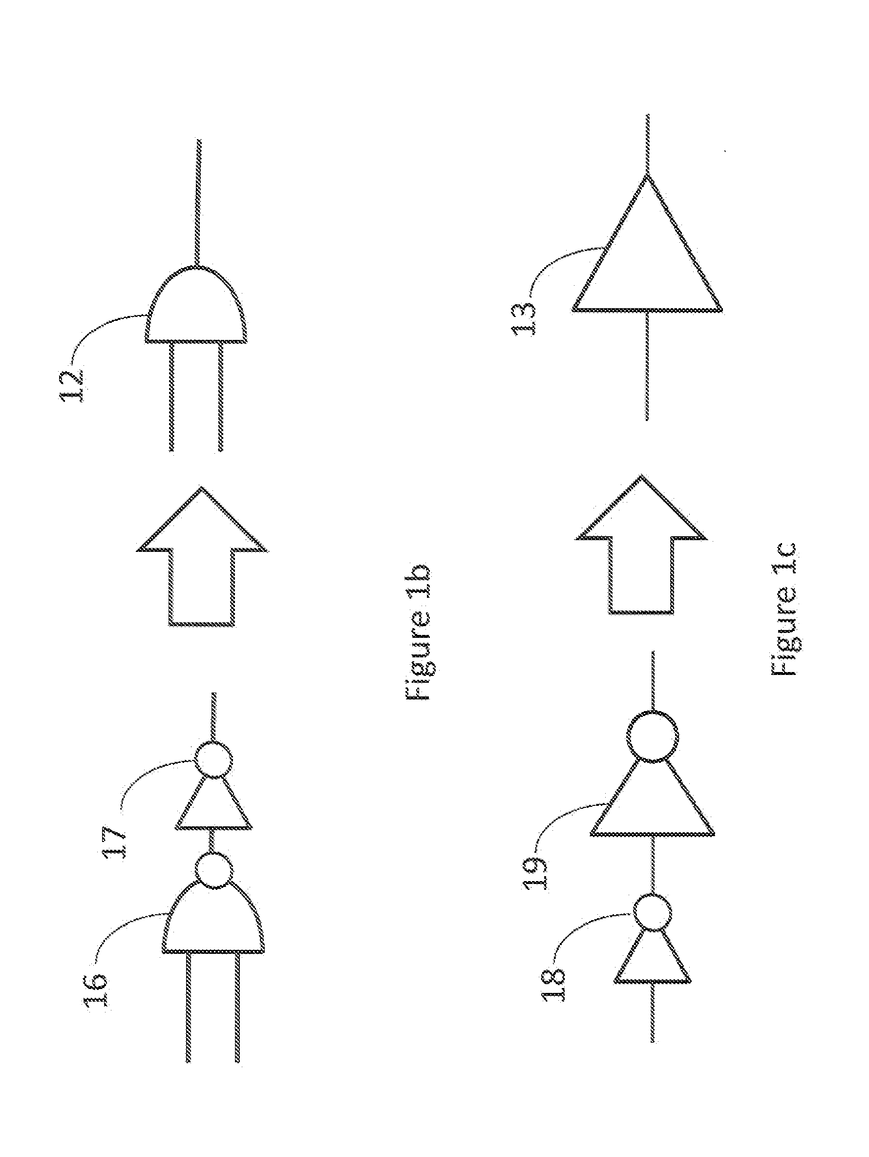
[0005]In one embodiment each flip-flop may be clocked by a clock distribution structure, where each branch of the clock distribution structure may contain tunable inverters, which may be tuned by varying either the capacitance or the resistance on the output of the inverter.

[0006]In another embodiment the variable capacitances and resistances may form a programmable memory where variable resistors may be programmed to vary the delay of the clock signals to each flip-flop. Furthermore, the memory may include structures for measuring the variable resistors and calibrating the memory programming structure.

[0007]In one embodiment, if the contents of the flip-flops may be observed and set in a manner similar to what was presented in U.S. Pat. No. 4,495,629 granted Jan. 22, 1985, to Zasio et al., diag...


PUM


Abstract

A memory-like structure composed of variable resistor elements for use in tuning respective branches and leaves of a clock distribution structure, which may be used to compensate for chip-by-chip and / or combinatorial logic path-by-path delay variations, which may be due, for example, to physical variations in deep submicron devices and interconnections, is presented. A single system clocked scan flip-flop with the capability to perform delay test measurements is also presented. Methods for measuring combinatorial logic path delays to determine the maximum clock frequency and delays to program the variable resistors, as well as methods for calibrating and measuring the programmed variable resistors, are also presented.

Description

FIELD OF THE INVENTION[0001]Embodiments of the present invention may relate to a process for creating and tuning clocks in a high speed synchronous deep submicron integrated circuit.BACKGROUND OF THE INVENTION[0002]Traditionally, tuning may have been primarily performed on memory clocks, as in U.S. Pat. No. 6,424,198 granted Jul. 23, 2002 to Wolford, or between chips as in U.S. Pat. No. 5,742,798 granted Apr. 21, 1998 to Goldrian, but on an integrated circuit (IC), tuning clocks has primarily consisted of configuring phase-locked loops (PLLs) or scan clocks, e.g., as presented in U.S. Pat. No. 7,719,315 granted May 18, 2010 to Ngo et al. Recently, in very deep submicron integrated circuit (IC) processes, the metal and semiconductor traces have become so small that the physical structures of their edges may dominate their electrical characteristics. In other words, from chip to chip, the variations in the lithographic processes of the individual wires and vias may vary their resistan...

Claims


Application Information

Patent Timeline
Patent Type & Authority Applications(United States)
IPC IPC(8): H03K5/15
CPCH03K5/15013H03K5/15H03K5/131H03K5/133H03K2005/00065H03K2005/00247
Inventor COOKE, LAURENCE H.
Owner COOKE LAURENCE H
Why Eureka
Try Eureka