Production method of rotary electric machine

a technology of rotary electric machines and production methods, which is applied in the direction of manufacturing tools, metal working apparatuses, and capacitors, can solve the problems of generating porosity and other problems, and achieve the effect of high joint strength and higher joint strength

Active Publication Date: 2014-11-20
HONDA MOTOR CO LTD
View PDF8 Cites 8 Cited by
  • Summary
  • Abstract
  • Description
  • Claims
  • Application Information

AI Technical Summary

Benefits of technology

[0015]According to the present invention, the leading end of the fusion zone can be arranged leaning to one side of either of the two adjacent electrical conductors. In other words, the porosity generation site of rhomboidal shape in the leading end of the fusion zone can be arranged leaning to one side of either of the two adjacent electrical conductors. The surface area of the porosity generation site on the joining face can thereby be made smaller, and the effective depth of the fusion zone on the joining face that is effective in joining can be kept deeper. Therefore, a higher joint strength is obtained compared to conventionally.
[0018]It is thereby possible to more reliably maintain the effective depth of the fusion zone on the joining face to be deeper by between the leading end parts of the two adjacent electrical conductors being made within the laser irradiation range, and thus a higher joint strength is obtained.
[0021]It is thereby possible to arrange the porosity generation site of rhomboidal shape in the leading end of the fusion zone to lean further to one side of either of the two adjacent electrical conductors. Therefore, the effective depth of the fusion zone on the joining face can be maintained deeper, and high joint strength is obtained more reliably.
[0022]According to the present invention, it is possible to provide a production method of rotary electric machines that can laser weld with higher joint strength than conventionally the leading end parts of a plurality of electrical conductors projecting from each slot.

Problems solved by technology

However, with laser welding, since the energy density at the leading end of the fusion zone is high, bubbles called porosity tend to generate in the leading end of the fusion zone.

Method used


Image

  • Production method of rotary electric machine
  • Production method of rotary electric machine
  • Production method of rotary electric machine

Examples


Embodiment Construction

[0032]Hereinafter, an embodiment of the present invention will be explained in detail while referencing the drawings.

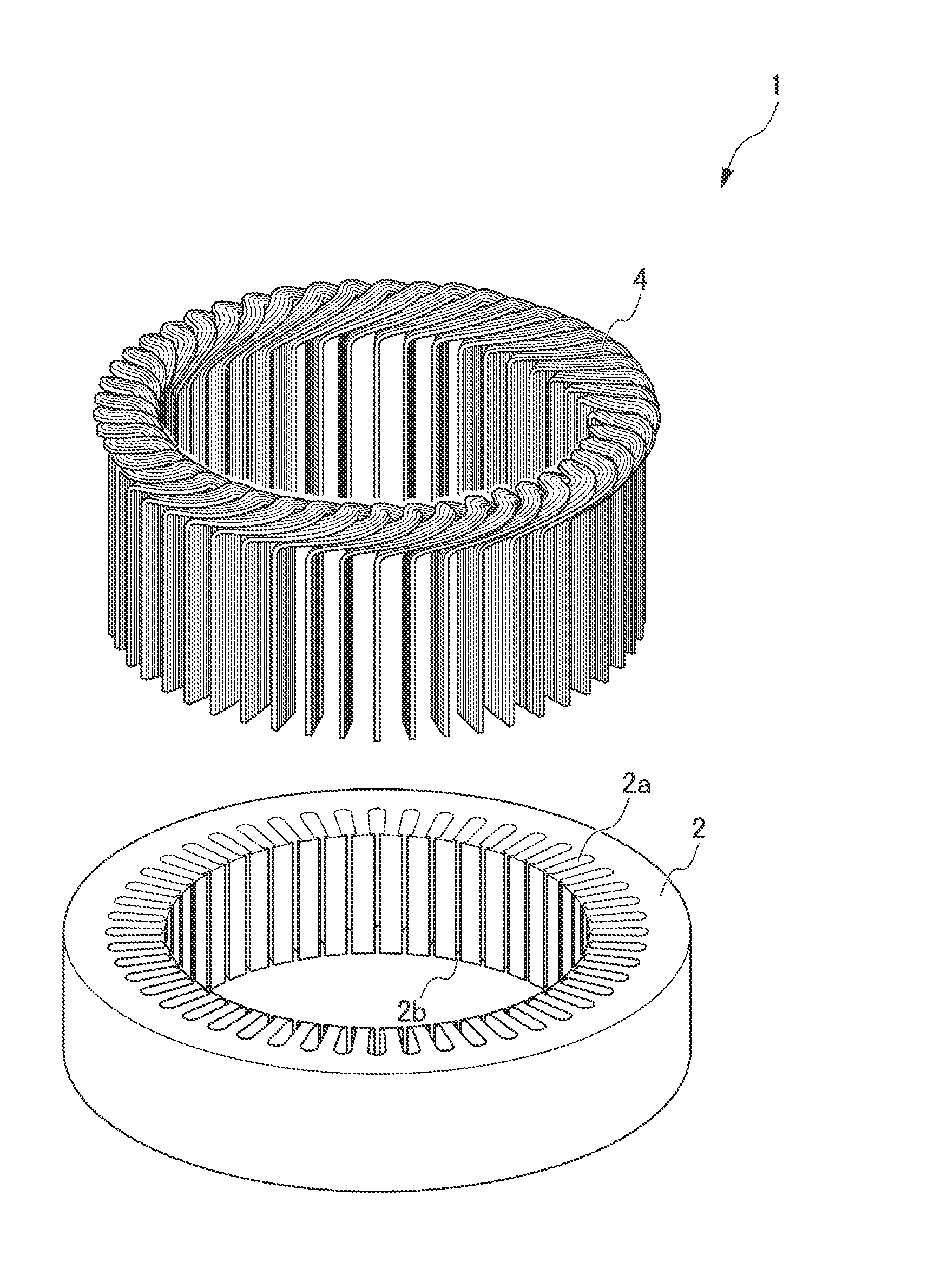
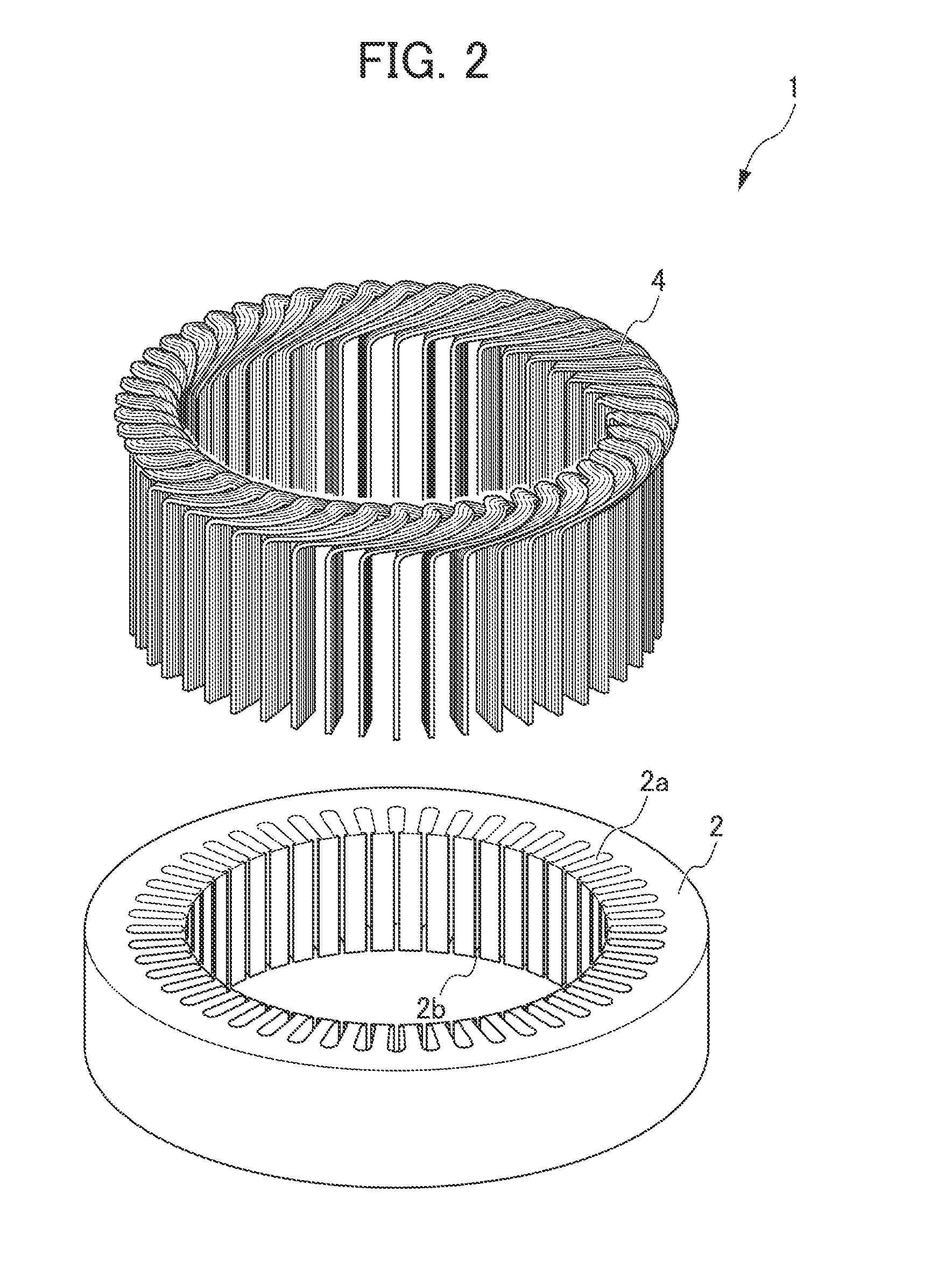
[0033]A production method of rotary electric machines according to the present embodiment produces a rotary electric machine by joining the leading end parts of a plurality of electrical conductors inserted into respective slots provided in a stator core and projecting from the respective slots, by way of laser welding.

[0034]First, the configuration of the rotary electric machine produced by the production method according to the present embodiment will be explained.

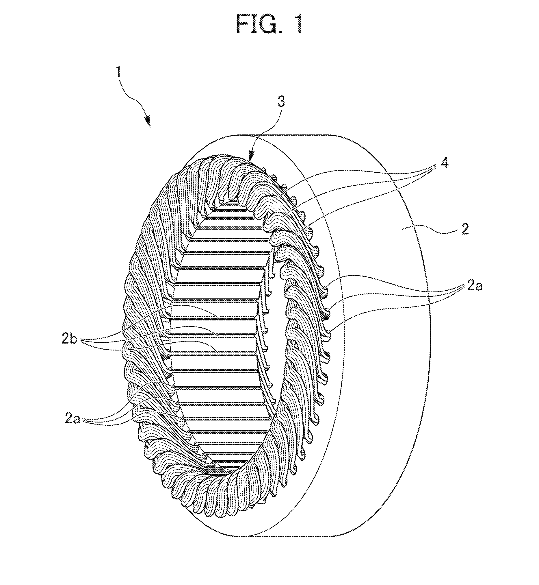
[0035]FIG. 1 is a perspective view showing the configuration of a stator 1 of a rotary electric machine according to the present embodiment. As shown in FIG. 1, the stator 1 is formed in an annular shape. At the inside of the stator 1, a rotor (not illustrated) is arranged to freely rotate, whereby the rotary electric machine is configured.

[0036]The stator 1 is configured to include a stator core 2 and coi...


PUM

PropertyMeasurementUnit
widthaaaaaaaaaa
widthaaaaaaaaaa
widthaaaaaaaaaa

Abstract

A production method of rotary electric machines is provided that can laser weld the leading end parts of a plurality of electrical conductors projecting from respective slots with high joint strength. A production method of rotary electric machines that produces a rotary electric machine by joining, by way of laser welding, leading end parts 41 of a plurality of electrical conductors 40 inserted in respective slots 2a provided in a stator core 2 and projecting from the respective slots 2a, includes the steps of matching and arranging the leading end parts 41 of two adjacent electrical conductors 40; and joining the leading end parts 41 of the two adjacent electrical conductors 40 by irradiating a laser onto the two adjacent electrical conductors 40 from a direction sloped at an angle θ relative to a joining face X of the leading end parts 41 of the two adjacent electrical conductors 40.

Description

[0001]This application is based on and claims the benefit of priority from Japanese Patent Application No. 2013-105408, filed on 17 May 2013, the content of which is incorporated herein by reference.BACKGROUND OF THE INVENTION[0002]1. Field of the Invention[0003]The present invention relates to a production method of a rotary electric machine.[0004]2. Related Art[0005]Conventionally, rotary electric machines such as electric motors and power generators that include a stator and rotor have been known. The stator of a rotary electric machine is usually produced in the following way.[0006]First, a plurality of coil elements in which a plurality of electrical conductors is bundled to form a substantially U-shape is prepared. Next, the plurality of coil elements thus prepared is aligned in an annular shape while layering in a circumferential direction, and in this state, the leading end part of each electrical conductor is inserted in each slot provided in an annular shape to the stator ...

Claims


Application Information

Patent Timeline
Patent Type & Authority Applications(United States)
IPC IPC(8): B23K26/22H02K15/085
CPCH02K15/085B23K26/22H02K15/0081B23K26/21Y10T29/49009Y10T29/4921Y10T29/49179B23K2101/38H01R43/0207H01R43/0221H01R43/0214
Inventor NISHIYAMA, TOMOKATSUTAKEDA, KAZUTOSHIONDA, HIDEAKI
Owner HONDA MOTOR CO LTD
Why Eureka
Try Eureka