Etching apparatus

a technology of etching apparatus and etching tube, which is applied in the direction of electrical apparatus, electric discharge tube, basic electric elements, etc., to achieve the effect of reducing the depth of etching

Active Publication Date: 2014-11-20
CANON ANELVA CORP
View PDF10 Cites 1 Cited by
  • Summary
  • Abstract
  • Description
  • Claims
  • Application Information

AI Technical Summary

Benefits of technology

[0011]The present invention provides a technique advantageous in reducing etching depth nonuniformity in the radial method of a tray and / or the radial direction of a substrate when etching a plurality of substrates accommodated in the tray.

Problems solved by technology

However, Japanese Patent Laid-Open No. 10-20473 discloses nothing about prevention of differences in etching depth between a substrate accommodated in a central portion of a tray and a substrate accommodated in a peripheral portion of the tray when etching a plurality of substrates accommodated in one tray.
However, Japanese Patent Laid-Open No. 2007-109770 discloses nothing about prevention of differences in etching depth between a substrate accommodated in a central portion of the tray and a substrate accommodated in a peripheral portion of the tray when etching a plurality of substrates accommodated in one tray.

Method used


Image

  • Etching apparatus
  • Etching apparatus
  • Etching apparatus

Examples


first embodiment

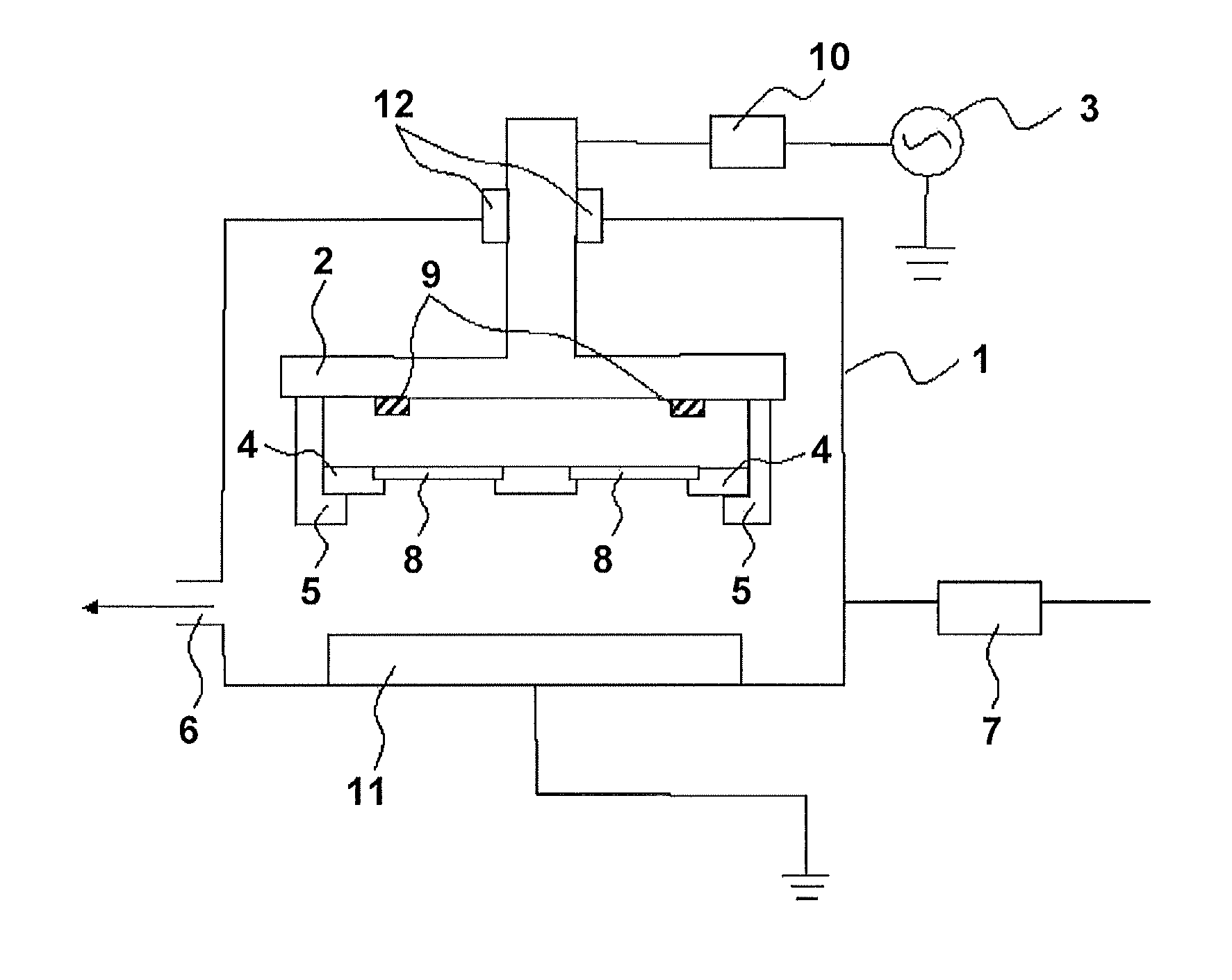
[0050]FIG. 1 is a schematic sectional view of a first etching apparatus according to the first embodiment. As shown in FIG. 1, the first etching apparatus includes, as main constituent elements, a chamber 1 capable of evacuation and a first electrode 2 to which power is applied. In addition, the etching apparatus includes a power supply 3 for applying power required for an etching process to the first electrode 2. In the chamber 1, the first electrode 2 including clamps 5 (members made of a metal compound such as alumina) which hold a tray 4 (for example, a member made of a metal compound such as alumina) holding substrates 8 is mounted through an insulator 12 (for example, a resin such as Teflon®). The insulator 12 is a member which electrically insulates the chamber 1 and the first electrode 2. The first electrode 2 includes a tray support portion capable of supporting the outer peripheral edge portion of the tray 4. The tray 4 can hold a plurality of substrates 8, and can be load...

second embodiment

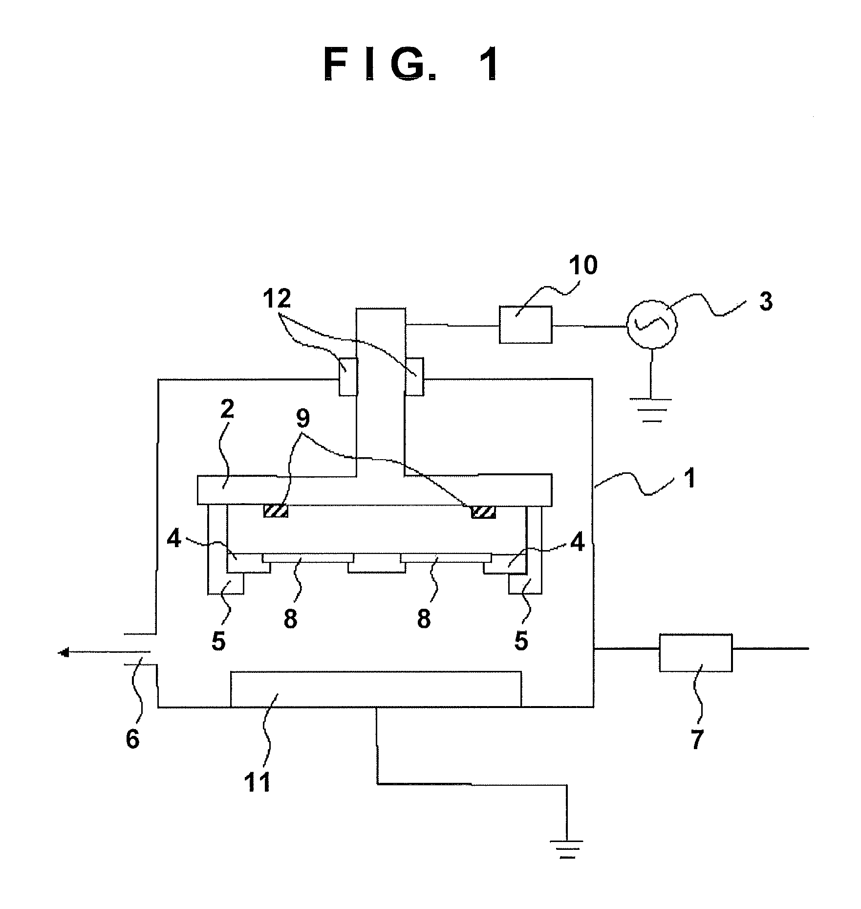
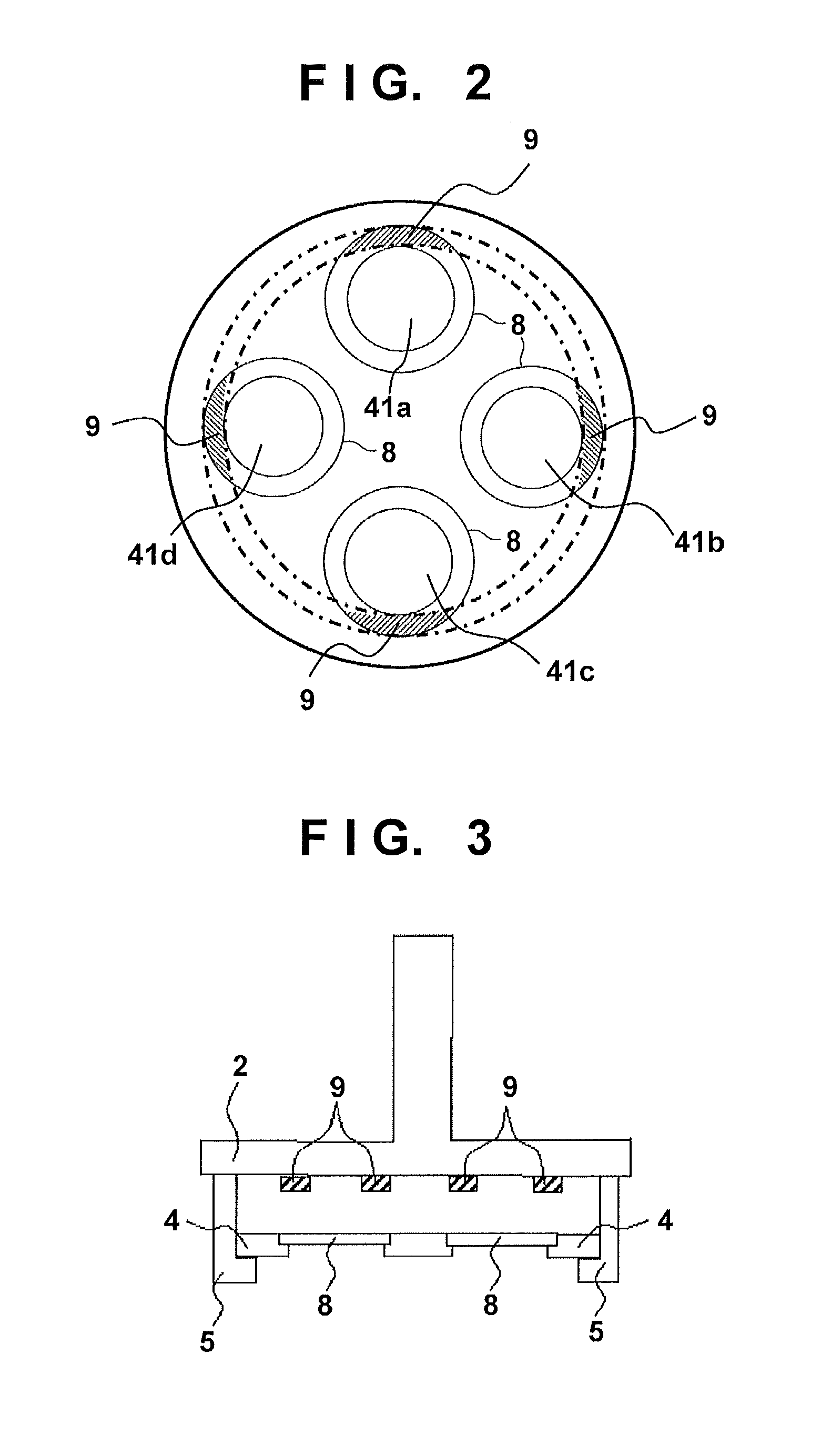
[0054]FIG. 3 is a schematic sectional view of a first electrode 2 according to the second embodiment. The basic arrangement is the same as that in the first etching apparatus. As shown in FIG. 6, a tray 4 holds four substrates at equal angular intervals around the center of the tray 4. In the second embodiment, as shown in FIG. 4, it is possible to improve the nonuniformity of an etching distribution in the radial direction of each substrate by attaching dielectric plates 9 along the peripheral edge portion of the obverse surface of a first electrode 2 so as to face the peripheral edge portions of the non-target surfaces of the four substrates provided on the peripheral portion of the tray 4. In the second embodiment, the first electrode 2 serves as the upper electrode (a second electrode 11 (not shown) serves as the lower electrode). When, however, the first electrode 2 serves as the lower electrode (the second electrode 11 (not shown) serves as the upper electrode), this embodimen...

third embodiment

[0055]FIG. 7 is a schematic sectional view of a first electrode according to the third embodiment. The basic arrangement of the third embodiment shown in FIG. 7 is the same as that of the etching apparatus in FIG. 1 described above. As shown in FIG. 11, a tray 4 holds a first substrate in the center of the tray 4, and at least four second substrates at equal angular intervals around the center of the tray 4. The tray 4 shown in FIG. 11 is provided with a plurality of substrate accommodation holes 41a, 41b, 41c, 41d, and 41e extending through the tray 4 in the thickness direction of substrates 8, and substrate holding portions 42a, 42b, 42c, 42d, and 42e capable of holding the entire peripheral edge portions of the substrates 8. The substrate holding portions 42a, 42b, 42c, 42d, and 42e each may be provided so as to be capable of holding a part of the peripheral edge portion of the substrate 8. When holding the tray 4 with a first electrode 2 (upper electrode), it is preferable to us...


PUM

PropertyMeasurementUnit
voltageaaaaaaaaaa
thicknessaaaaaaaaaa
structureaaaaaaaaaa

Abstract

An etching apparatus includes a chamber capable of being evacuated, a first electrode provided in the chamber and including a tray support portion configured to support a tray which can hold a plurality of substrates and load/unload the substrates into/from the chamber, and a voltage applying unit configured to apply a voltage to the first electrode. A dielectric plate is attached to a portion, of an obverse surface of the first electrode, which faces an outer edge portion of a non-target surface of the substrate.

Description

BACKGROUND OF THE INVENTION[0001]1. Field of the Invention[0002]The present invention relates to an etching apparatus which etches a substrate while applying a voltage to an electrode.[0003]2. Description of the Related Art[0004]FIG. 21 is a view showing a schematic arrangement of the dry etching apparatus disclosed in Japanese Patent Laid-Open No. 10-20473. FIG. 22A is a plan view of the lower electrode structure of the dry etching apparatus. FIG. 22B is a sectional view of FIG. 22A. FIG. 23 shows an etching rate distribution within a wafer plane in the first embodiment disclosed in Japanese Patent Laid-Open No. 10-20473 in comparison with a conventional apparatus. Electrodes 811 and 812 are arranged in an etching chamber 810 so as to face each other. The upper electrode 811 is grounded. The lower electrode 812 on which a semiconductor wafer 813 as a target substrate is mounted is connected to a high-frequency power supply 815 via a matching circuit 814.[0005]A conventional etching...

Claims


Application Information

Patent Timeline
Patent Type & Authority Applications(United States)
IPC IPC(8): H01J37/32
CPCH01J37/32807H01J37/32532H01L21/6838H01J37/32385H01J37/32541H01J37/32568H01J37/32577H01J2237/334H01J2237/3341H01J37/32715
Inventor SUZUKI, HIDEKAZUSHIBAGAKI, MASAMISEKIGUCHI, ATSUSHI
Owner CANON ANELVA CORP
Why Eureka
Try Eureka