Method for recovery of hydrocarbon fluid

a hydrocarbon fluid and recovery method technology, applied in the field of hydrocarbon fluid recovery method, can solve the problems of limiting the hydrocarbon recovery considerably, limiting the mobility of fluids in the reservoir, and risk of ground structure fragmentation, so as to increase the hydrocarbon recovery factor

Inactive Publication Date: 2014-11-20
IMPACT TECH SYST
View PDF5 Cites 16 Cited by
  • Summary
  • Abstract
  • Description
  • Claims
  • Application Information

AI Technical Summary

Benefits of technology

[0012]It is therefore an object of embodiments of the present invention to overcome or at least reduce some or all of the above-described disadvantages of the known methods for hydrocarbon recovery operations by providing procedures to increase the hydrocarbon recovery factor.

Problems solved by technology

The capillary resistance causes a creation of preferred fluid pathways in the porous media (breakthrough), which limits the hydrocarbon recovery considerably.
Thus, capillary resistance limits the mobility of the fluids in the reservoir.
Disadvantages of these systems are the risk of fragmentation of the ground structure as well as difficulties in controlling the impact and limited effectiveness of the methods.
However, such violent excitations by explosives, earthquakes and the like are often also seen to cause deterioration of the ground structure that may decrease the hydrocarbon recovery over longer time.
The application of pressure pulses has by some been reported to enhance the flow rates through porous media, but has however also been reported to increase the risk of water breakthrough and viscous fingering in fluid injection operations.
In pipe systems Water Hammering may result in problems from noise and vibration to breakage and pipe collapse.

Method used


Image

  • Method for recovery of hydrocarbon fluid
  • Method for recovery of hydrocarbon fluid
  • Method for recovery of hydrocarbon fluid

Examples


Embodiment Construction

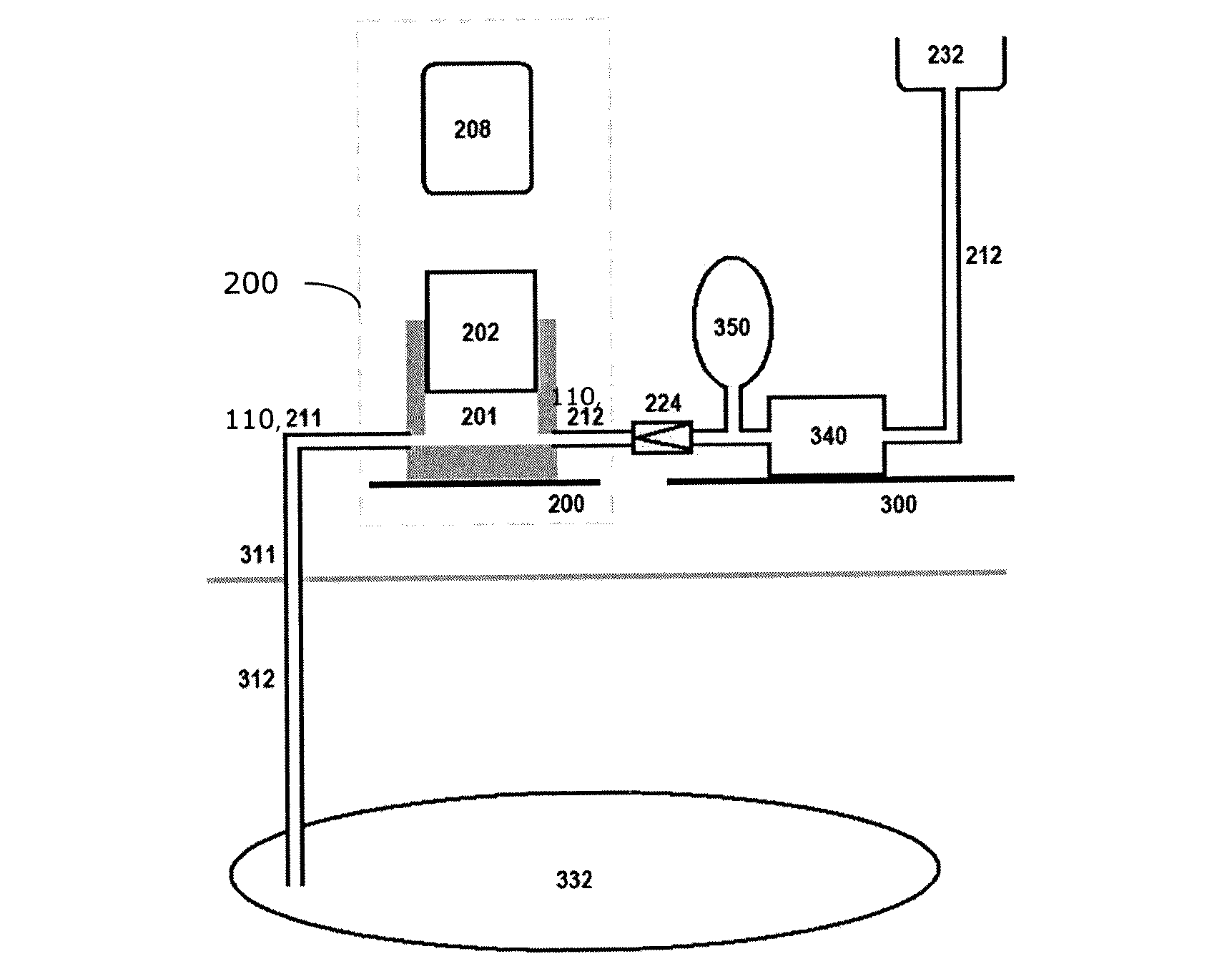
[0080]Impact pressures are like propagating pressure shocks in a fluid and are generated by a collision process,—either by a solid object in motion colliding with the fluid, or by a flowing fluid colliding with a solid. The latter describes the Water Hammer phenomenon where momentum of the flowing fluid is converted into impact pressures in the fluid.

[0081]The physics of a collision process between a solid and a fluid is in the following described in more detail, first by looking at collisions between solid objects analysed from an idealized billiard ball model.

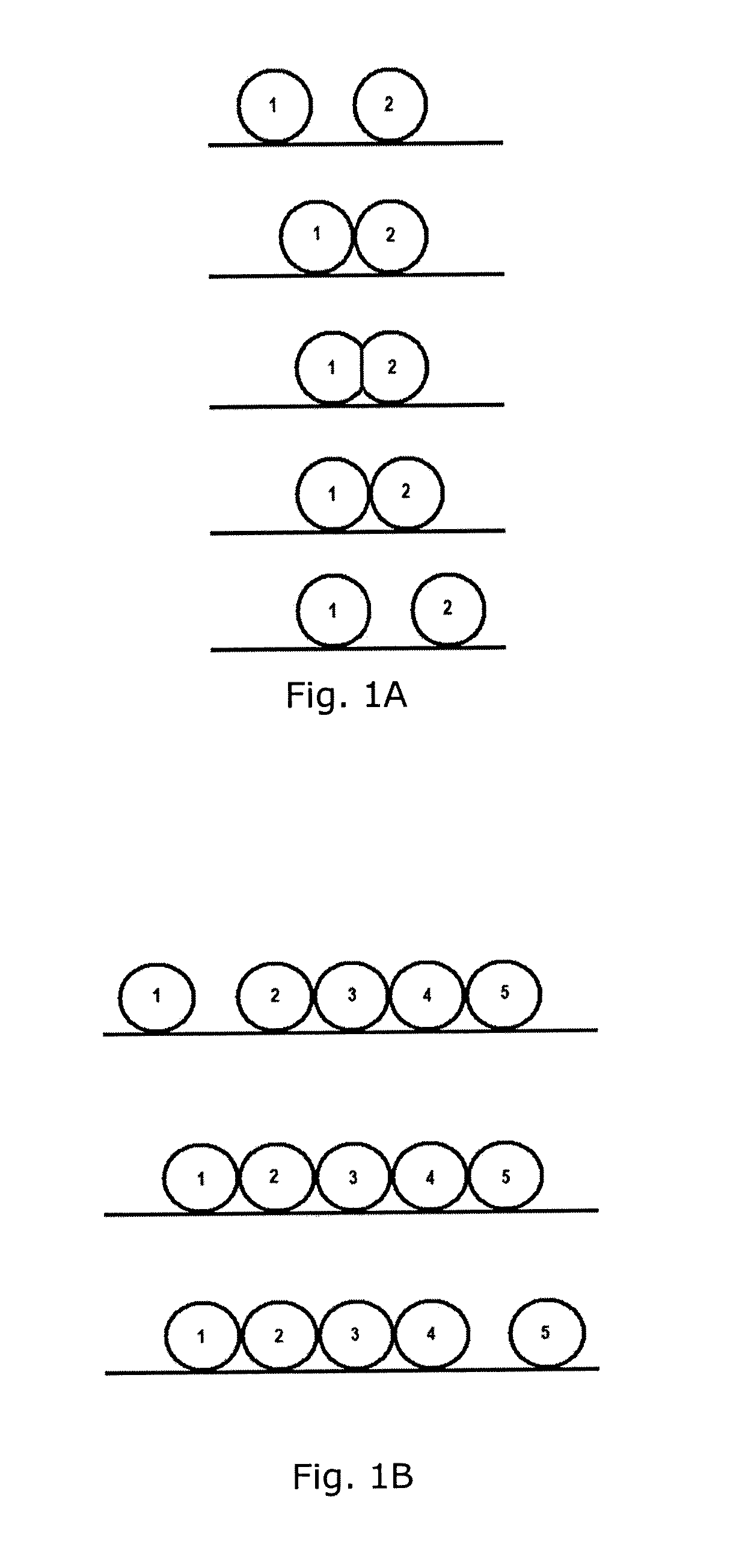
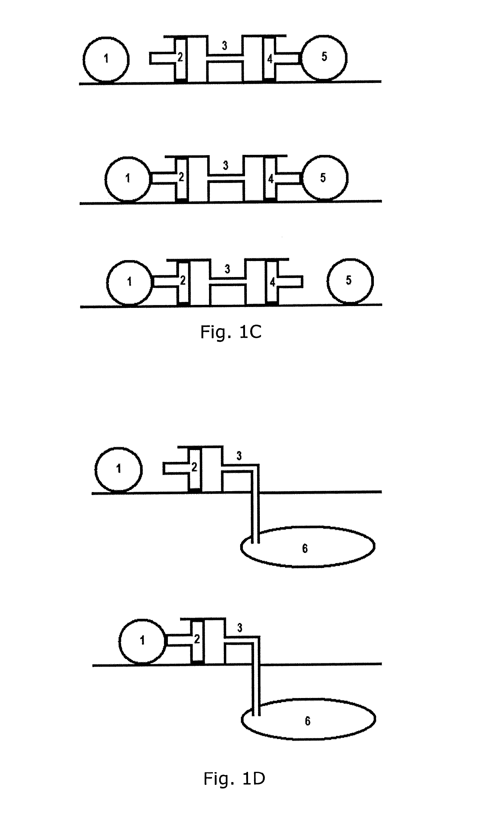
[0082]The billiard ball model is outlined in FIG. 1A illustrating different stages during a collision process between two billiard balls 1 and 2. The stages shown in this figure are from the top; 1) the stage of ball 1 moving with speed U towards ball 2 at rest, 2) the time of first contact, 3) the time of maximum compression (exaggerated), 4) the time of last contact, and 5) the stage of ball 2 moving with speed U and ball 1...


PUM


Abstract

A method is described for recovery of a hydrocarbon fluid from a porous medium by injection of a fluid into the porous medium. The method includes determining a Rayleigh time on the basis of the density of the fluid and the hydrocarbon fluid, the median pore diameter of the porous medium, and surface tension between the fluid and the hydrocarbon fluid. Further, pressure stimulation is provided in the fluid and generated by a collision process with a collision contact rise time which is of the range of 1-100 times the Rayleigh time. Alternatively or additionally, the providing a pressure stimulation in the fluid include generating an impact pressure with a pressure amplitude I and a pressure rise time Δt, where the pressure amplitude is larger than the relation γcΔt/a2, where γ is the surface tension between the fluid and the hydrocarbon fluid, and c is the speed of sound in the porous media. In aspects of the invention, the method includes arranging a chamber in fluid communication with the porous medium via at least one conduit, and having the chamber comprising first and second wall parts movable relative to each other. The pressure stimulation includes providing an impact pressure in the fluid to propagate to the porous medium via the conduit, and where the impact pressure is generated by the collision process between an object arranged outside of the fluid and the first wall parts for the first wall part to impact on the fluid in the chamber.

Description

FIELD OF THE INVENTION[0001]The present invention relates to a method for recovery of a hydrocarbon fluid from a porous medium.BACKGROUND OF THE INVENTION[0002]Hydrocarbon recovery operations may in general involve a broad range of processes involving the use and control of fluid flow operations for the recovery of hydrocarbon from subterranean formations, including for instance the inserting or injection of fluids into subterranean formations such as treatment fluids, consolidation fluids, or hydraulic fracturing fluids, water flooding operations, drilling operations, cleaning operations of flow lines and well bores, and cementing operations in well bores.[0003]Subterranean reservoir formations are porous media comprising a network of pore volumes connected with pore throats of difference diameters and lengths. The dynamics of fluid injection into the reservoirs to displacing the fluids in the porous ground structure in a reservoir has been studied extensively in order to obtain im...

Claims


Application Information

Patent Timeline
Patent Type & Authority Applications(United States)
IPC IPC(8): E21B49/00E21B47/00
CPCE21B47/00E21B49/008E21B28/00E21B43/00E21B43/16E21B43/25E21B43/003
Inventor PAULSEN, JIM-VIKTOR
Owner IMPACT TECH SYST
Why Eureka
Try Eureka