
Systems, methods and apparatuses for direct embossment of a polymer melt sheet

a technology of polymer melt and embossing method, applied in the field of systems, can solve the problems of blockage, difficult, if not impossible, to separate polymer interlayer sheets, and difficult to separate sheets or blanks back into individual pieces without blockag

Inactive Publication Date: 2014-11-27
SOLUTIA INC
View PDF8 Cites 5 Cited by
  • Summary
  • Abstract
  • Description
  • Claims
  • Application Information

AI Technical Summary

Benefits of technology

The conventional processes of manufacturing multiple layer glass panels using embossing processes were costly, inefficient, and required large space. The process involved multiple cooling and reheating steps, which resulted in increased energy costs and lowered production efficiency. Additionally, a multi-stage, multi-set embossing roller set-up was required for both sides of the polymer interlayer sheet. The patent aims to address these issues by providing a more efficient and cost-effective process.

Problems solved by technology

Generally, two (2) common problems are encountered in the art of manufacturing multiple layer glass panels: blocking and de-gassing.
Blocking can be a problem during the manufacturing, storage and distribution of polymer interlayer sheets, where it is not uncommon for the polymer interlayer sheets (which in some processes are stored in rolls) to come into contact with each other.
Blocking can also pose a problem post-manufacturing, namely after the point-of-sale of the polymer interlayer sheets.
If a polymer interlayer is susceptible to blocking, it can be difficult, if not impossible, to separate the polymer interlayer sheets.
For example, it may be difficult to separate the sheets or blanks back into individual pieces without deforming or stretching the sheet or blank once they are stacked.
However, these technologies are not always effective in removing all of the air trapped in the interstitial spaces between the substrates, especially when the polymer interlayer sheet has a smooth surface.
These bubbles and gaseous pockets are undesirable and problematic where the end-product multiple layer glass panel will be used in an application where optical quality is important.
It is not an uncommon defect in the art of multiple layer glass panels for dissolved gases to appear (e.g., for bubbles to form) in the panel over time, especially at elevated temperatures and under certain weather conditions and sunlight exposure.
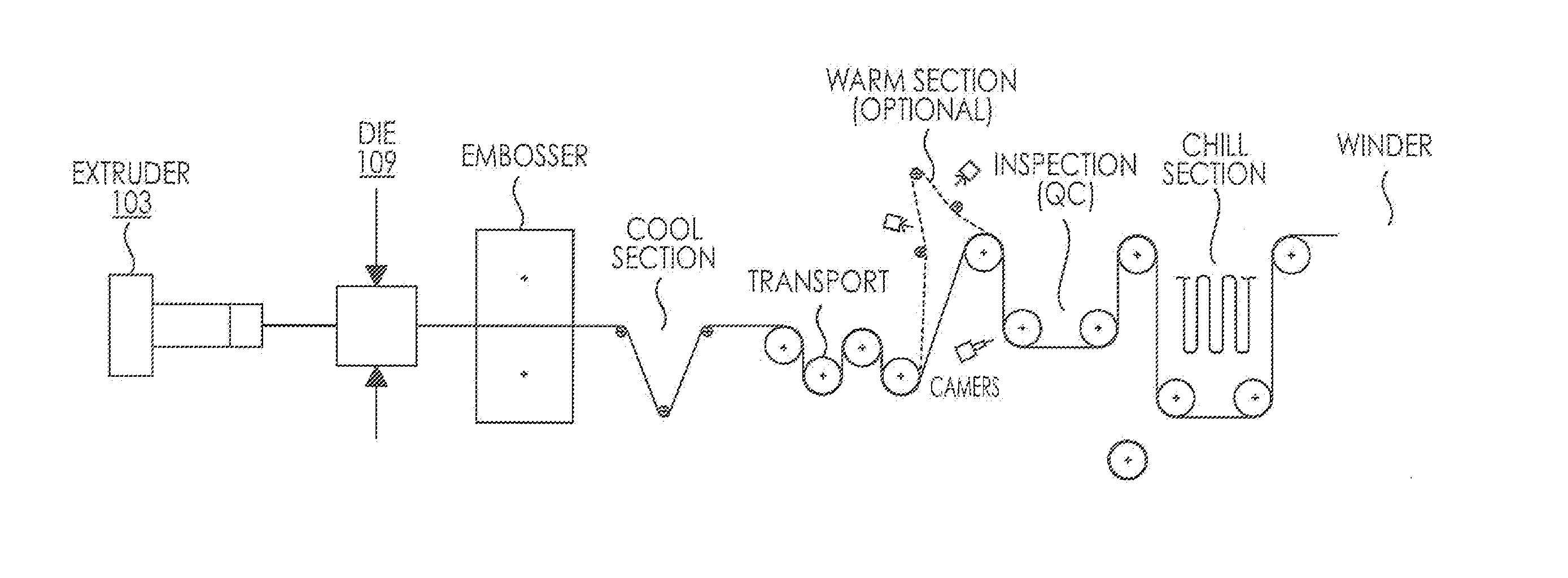
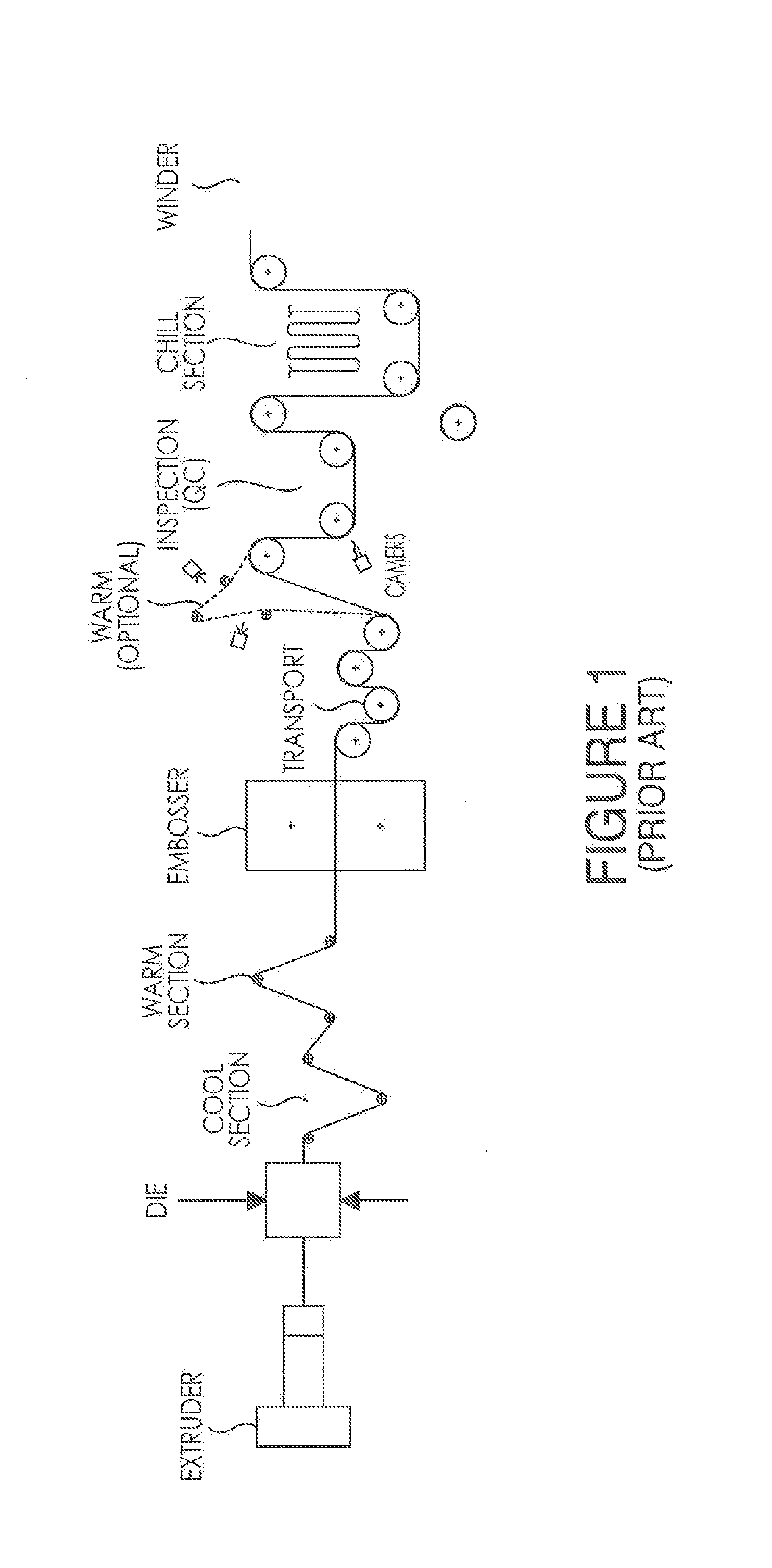
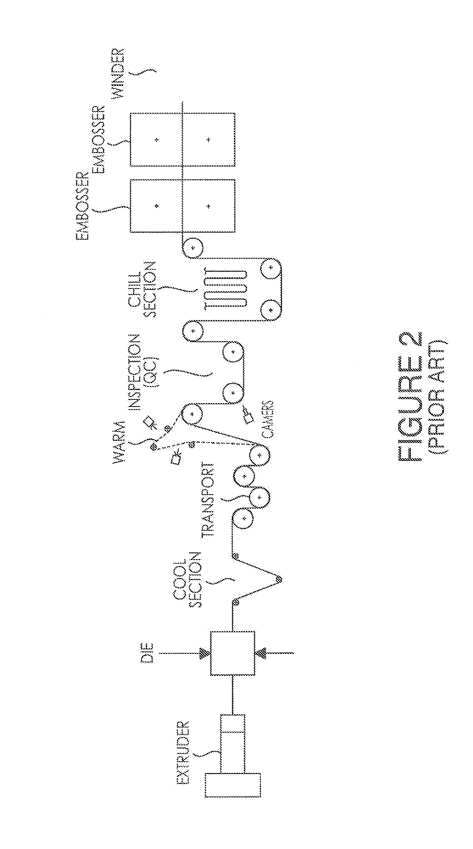
While certain embossing methods and techniques in the manufacture of multiple layer glass panels are known, there are several problems with the embossing processes previously utilized in the art (referred to herein as “Conventional Processes”).
The first of these problems is the general inefficiency of the Conventional Processes.
These additional production steps could significantly add to the costs, energy intake and the overall space required for multiple layer glass panel production.
As noted previously, in some Conventional Processes, the polymer interlayer sheet is not embossed directly after it leaves the extrusion die while it is still a melt because the molten polymer will stick to the embossing rolls causing a mess and degrading the integrity of the polymer interlayer sheet, rendering it unusable.
However, a completely cooled polymer interlayer sheet is difficult, if not impossible, to emboss, therefore, in some Conventional Processes, after the polymer melt is cooled to a polymer interlayer sheet, the surface of the interlayer sheet must be reheated with the embossing roller (or by some other technique) at the time of embossing.
These properties of the Conventional Processes resulted in increased energy costs for the entire manufacturing system (e.g., the energy costs associated with the cooling of the polymer interlayer sheet and the energy costs associated with the extra steps in the manufacturing process), larger space and footprint requirements for the manufacturing system (more steps require more space), decreased efficiency and overall output due to the longer manufacturing process, and higher investment costs for the process as a whole.

Method used


Image

  • Systems, methods and apparatuses for direct embossment of a polymer melt sheet
  • Systems, methods and apparatuses for direct embossment of a polymer melt sheet
  • Systems, methods and apparatuses for direct embossment of a polymer melt sheet

Examples


example 1

[0069]

TABLE 1EmbossedMeasurementsMeasurementsPermanenceSurfaceEmbossingof Embossingof EmbossingMeasured atRetentionRolleron Polymeron PolymerMottle100° C. for100° C. forSamplePatternSide 1Side 2(CMA)5 minutes5 minutesNE A—Rz: 14Rz: 130.2Rsm: 528Rsm: 465CP ARz: 90Rz: 56Rz: 570.39682Rsm: 249Rsm: 298Rsm: 294DP ARz: 90Rz: 64Rz: 44010097Rsm: 249Rsm: 271Rsm: 286NE B—Rz: 37Rz: 373.3Rsm: 830Rsm: 889CP BRz: 90Rz: 49Rz: 502.06986Rsm: 249Rsm: 313Rsm: 367DP BRz: 90Rz: 74Rz: 641.5101102Rsm: 249Rsm: 288Rsm: 280NE C—Rz: 49Rz: 505.2Rsm: 910Rsm: 868CP CRz: 90Rz: 57Rz: 583.05888Rsm: 249Rsm: 323Rsm: 364DP CRz: 90Rz: 74Rz: 650.7101102Rsm: 249Rsm: 285Rsm: 272

[0070]Example 1 demonstrates that the Disclosed Process consistently has better permanence and embossed surface retention (higher values) of the embossed surfaces regardless of the original surface roughness of the sheet. In this Example, “A”“B” and “C” represent test sheets with different roughness values as formed directly out of the extrusion die...

example 2

[0071]

TABLE 2EmbossedEmbossedMeasurementsSurfaceSurfaceStackEmbossingof EmbossingMeasurementsRetentionRetentionStickingRolleron Polymerof Embossing onMottle100° C. for140° C. forPeel ForceSamplePatternSide 1Polymer Side 2(CMA)5 minutes5 minutes(g / cm)NE—Rz: 13Rz: 131.00103104807Rsm: 365Rsm: 398CP XRz: 90Rz: 54Rz: 54.60724959Rsm: 249Rsm: 285Rsm: 287CP YRz: 90Rz: 52Rz: 51.60695264Rsm: 249Rsm: 292Rsm: 288CP ZRz: 90Rz: 48Rz: 47.73654970Rsm: 249Rsm: 294Rsm: 282DPRz: 90Rz: 61Rz: 54.191019023Rsm: 249Rsm: 290Rsm: 275

[0072]Table 2 depicts a comparison of a non-embossed sheet and a sheet embossed by the Disclosed Process with sheets embossed by the Conventional Processes (“X”“Y” and “Z”) for which the process variables of line speed, embossing roller temperature and force applied to the sheet by the rollers were varied in an attempt to attain the same measured embossed values as those obtained on the sheet formed by the Disclosed Process. Embossed surface retention of the samples was measured ...

example 3

[0073]

TABLE 3EmbossedSurfaceRetention140° C. for 30SampleRzminutesNE1394CP5340DP5477

[0074]Table 3 depicts the results from comparison testing at the extreme testing conditions for embossed surface retention (140° C. for thirty (30) minutes). As shown in Table 3, the embossed surface retention value for the Disclosed Process is significantly higher than that of the Conventional Process even in extreme testing conditions and closer to non-embossed (random rough) surfaces.

[0075]The improved embossed surface retention values of various polymer interlayer sheets embossed by the Disclosed Process in comparison to the Conventional Process over multiple testing conditions is graphically depicted in FIG. 7. FIG. 7 provides a line graph of comparative embossed surface retention values for multiple different samples of polymer interlayers embossed by the Disclosed Process and the Conventional Process. As can be seen in FIG. 7, no matter the sheet tested or the process variables manipulated, th...


PUM

PropertyMeasurementUnit
surface roughness Rzaaaaaaaaaa
temperatureaaaaaaaaaa

Abstract

A continuous single-stage embossing station comprised of two (2) temperature controlled engraved rollers which is located immediately after the extrusion die in the manufacturing process for multi-layer laminated glass panels and allows for dual simultaneous embossment of both sides of a polymer melt sheet and produces a polymer interlayer sheet with increased permanence, embossed retention values and decreased incidence of mottle and stack sticking peel force values. Also disclosed herein is an embossed polymer interlayer sheet with a first side, a second side and an embossed surface on at least one of the sides, with a surface roughness Rz of 10 to 90 microns on the embossed surface, a permanence of greater than 95% when tested at 100° C. for five (5) minutes and an embossed surface retention of greater than 70% when tested at 140° C. for five (5) minutes.

Description

CROSS REFERENCE TO RELATED APPLICATION(S)[0001]This application is a continuation of U.S. Non-Provisional application Ser. No. 13 / 069,121, filed on Mar. 22, 2011, currently pending, which claims the benefit of U.S. Provisional Patent Application Ser. No. 61 / 418,275, filed Nov. 30, 2010, now expired, the entire disclosure of which is incorporated by reference herein.BACKGROUND OF THE INVENTION[0002]1. Field of the Invention[0003]This disclosure is related to the field of polymer interlayers for multiple layer glass panels and multiple layer glass panels having at least one polymer interlayer sheet. Specifically, this disclosure is related to the field of systems, methods and apparatuses for embossing the polymer interlayer sheets of multiple layer glass panels immediately after the polymer interlayer sheets have left the extrusion die while they are polymer melt sheets.[0004]2. Description of Related Art[0005]Generally, multiple layer glass panels are comprised of two sheets of glass...

Claims


Application Information

Patent Timeline
Patent Type & Authority Applications(United States)
IPC IPC(8): B29C47/00B29C47/88B29C59/02B29C47/06B29C59/04B29C48/28
CPCB29C47/0061B29C47/065B29C59/04B29C59/022B29C2059/023B29K2101/12B29K2105/256B29K2995/0072B29C47/884B29C59/046B29C43/222B32B3/30B29C48/08B29C48/0011B29C48/28B29C48/91B29C48/914B29C2948/92295B29C2948/92438Y10T428/24355B29C48/002B29C48/21B29C48/9135
Inventor SPANGLER, LORAYACOVONE, VINCENT J.KARAGIANNIS, ARISTOTELISMATIS, GARYNAGARAJAN, PRATAPKUMARSMITHSZYDLOWSKI, WITOLDURBAN, RICHARDFENG, WENLAI
Owner SOLUTIA INC
Learn More