
Systems and methods for reducing magnetic resonance (MR) imaging acoustic noise in mr inflow imaging

a magnetic resonance imaging and acoustic noise technology, applied in the field of mri systems, can solve the problems of generating vibrations in the gradient coil, reducing patient comfort or increasing patient anxiety during the image acquisition process, and generating high-quality images by using relatively fast scan times. the effect of reducing acoustic nois

Active Publication Date: 2014-11-27
GENERAL ELECTRIC CO
View PDF7 Cites 7 Cited by
  • Summary
  • Abstract
  • Description
  • Claims
  • Application Information

AI Technical Summary

Benefits of technology

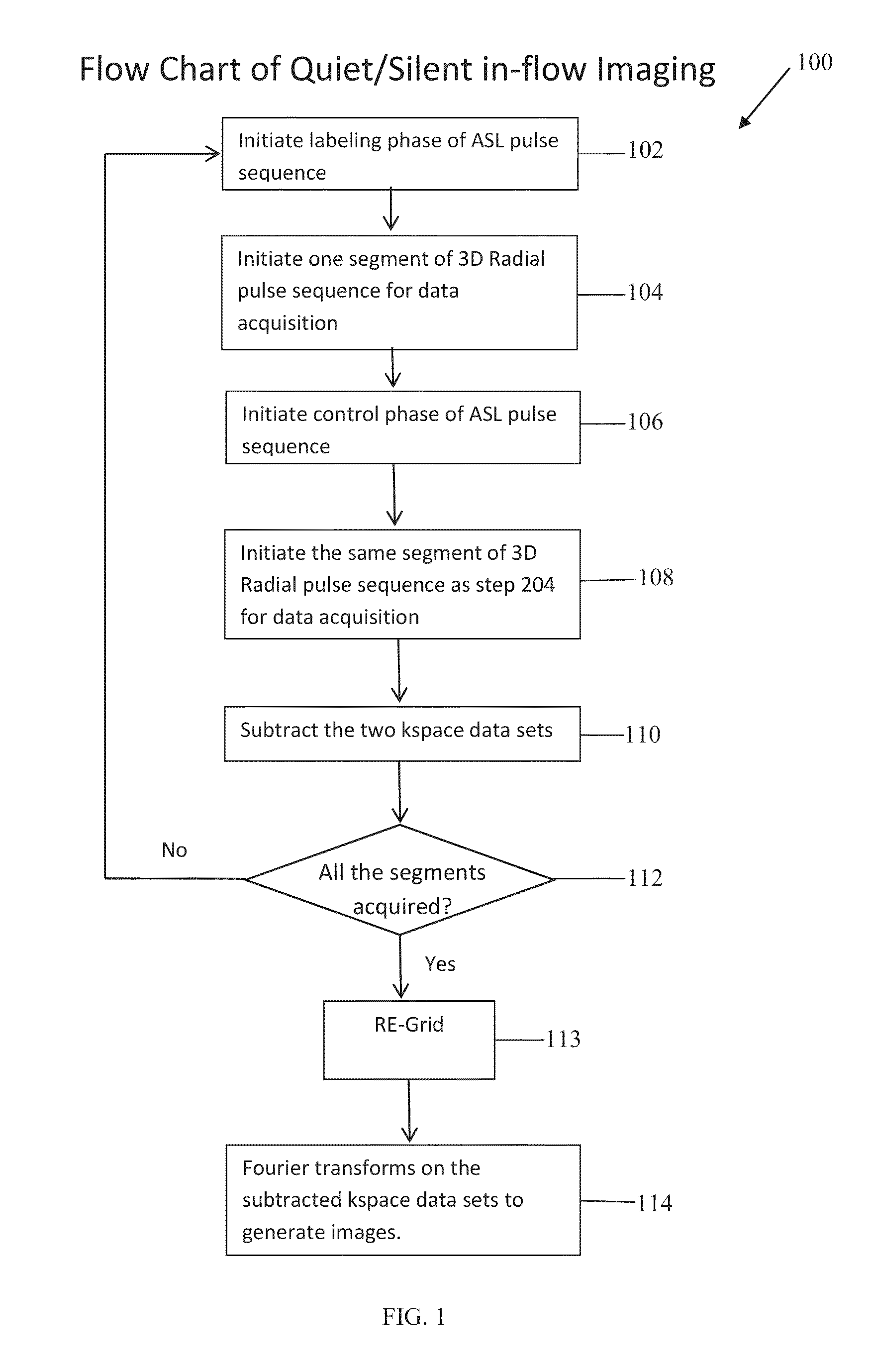
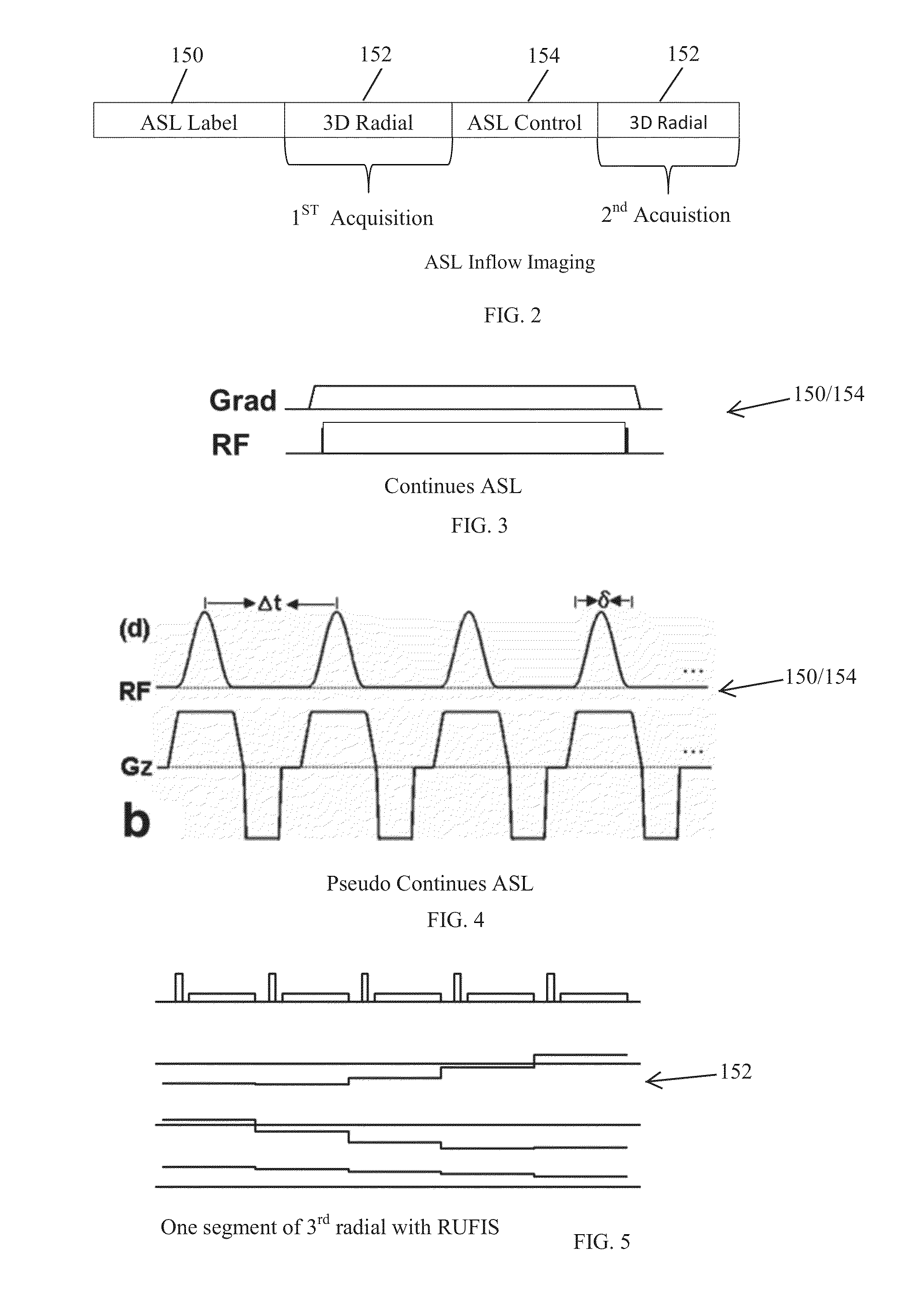
This patent describes a method and computer software for reducing noise in magnetic resonance imaging (MRI) scans. The method involves using a special technique called arterial spin labeling (ASL) and a three-dimensional (3D) radial pulse sequence to create tag or control images of a region of interest. These images are then combined to create a final image with reduced noise. The technical effect of this invention is improved image accuracy and quality.

Problems solved by technology

In some cases, an interaction between the main magnetic field and the current switching in the gradient coils may generate vibrations in the gradient coil.
As a result, the vibrations generated by the gradient coil, and potentially, a gradient coil support structure may create sound waves.
Moreover, generating high-quality images by using relatively fast scan times may also generate acoustic noise of a substantially high level.
The acoustic noise may therefore cause a decrease in patient comfort or an increase in patient anxiety during the image acquisition process.

Method used


Image

  • Systems and methods for reducing magnetic resonance (MR) imaging acoustic noise in mr inflow imaging
  • Systems and methods for reducing magnetic resonance (MR) imaging acoustic noise in mr inflow imaging
  • Systems and methods for reducing magnetic resonance (MR) imaging acoustic noise in mr inflow imaging

Examples


Embodiment Construction

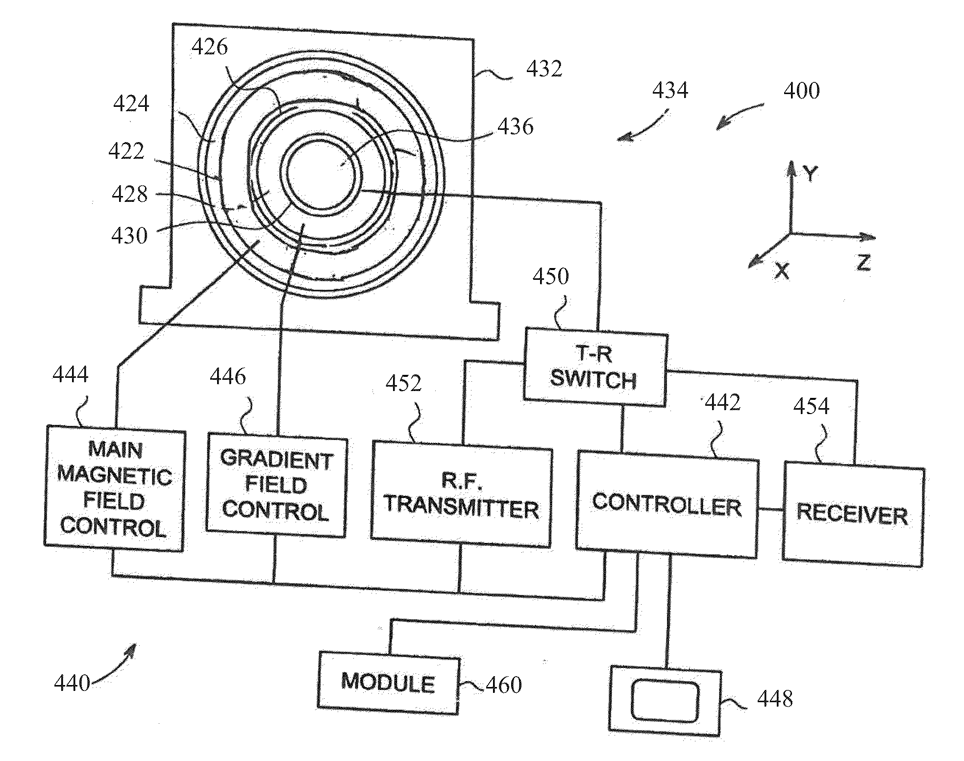
[0019]The following detailed description of certain embodiments will be better understood when read in conjunction with the appended drawings. To the extent that the figures illustrate diagrams of the functional blocks of various embodiments, the functional blocks are not necessarily indicative of the division between hardware. Thus, for example, one or more of the functional blocks may be implemented in a single piece of hardware or multiple pieces of hardware. It should be understood that the various embodiments are not limited to the arrangements and instrumentality shown in the drawings. Additionally, the system blocks in the various figures or the steps of the methods may be rearranged or reconfigured.

[0020]As used herein, an element or step recited in the singular and proceeded with the word “a” or “an” should be understood as not excluding plural of said elements or steps, unless such exclusion is explicitly stated. Furthermore, references to “one embodiment” are not intended...


PUM


Abstract

Systems and methods for reducing acoustic noise in a Magnetic Resonance Imaging (MRI) are provided. One method includes applying a labeling phase of an arterial spin labeling (ASL) pulse sequence to a region of interest, applying a three-dimensional (3D) radial pulse sequence to the region of interest to generate a tag image, applying a control phase of the ASL pulse sequence to the region of interest, and applying the 3D radial pulse sequence to the region of interest to generate a control image.

Description

BACKGROUND[0001]The subject matter disclosed herein relates generally to Magnetic Resonance Imaging (MRI) systems, and more particularly to methods and systems for reducing acoustic noise in MRI systems.[0002]MRI is a medical imaging modality that generates images of the inside of a human body without using x-rays or other ionizing radiation. MRI uses a main magnet to create a strong, uniform, static magnetic field (i.e., the “main magnetic field”) and gradient coils to produce smaller amplitude, spatially varying magnetic fields when a current is applied to the gradient coils. When a human body, or part of a human body, is placed in the main magnetic field, the nuclear spins that are associated with hydrogen nuclei in tissue water become polarized. The magnetic moments that are associated with these spins become preferentially aligned along the direction of the main magnetic field, resulting in a small net tissue magnetization along that axis (the “z axis,” by convention) and the g...

Claims


Application Information

Patent Timeline
Patent Type & Authority Applications(United States)
IPC IPC(8): G01R33/385G01R33/563
CPCG01R33/5635G01R33/3854G01R33/4826G01R33/56366
Inventor SUN, WEIWU, GAOHONG G.POLZIN, JASON ANDREWSHANKARANARAYANAN, AJIT
Owner GENERAL ELECTRIC CO
Learn More