
Portable electronic device with exposed heat dissipating mechanism

a technology of heat dissipation mechanism and electronic device, which is applied in the direction of electrical apparatus casing/cabinet/drawer, cooling/ventilation/heating modification, instruments, etc., can solve the problems of poor device performance, slow operation speed and operation shutdown, and reduce the useful life of electronic devices, so as to achieve effective heat dissipation and increase the thickness of portable electronic devices , the effect of increasing the thickness

Inactive Publication Date: 2014-11-27
CHAUN CHOUNG TECH
View PDF10 Cites 9 Cited by
  • Summary
  • Abstract
  • Description
  • Claims
  • Application Information

AI Technical Summary

Benefits of technology

The present invention is a portable electronic device with a heat dissipating mechanism. It uses cooling parts on the main body and on the outer housing to effectively dissipate the heat generated by the device. This improves the device's performance without increasing its thickness. The invention is suitable for various portable electronic devices that require efficient heat dissipation. It protects the device from poor performance, machine breakdown, and saves electronic components from damage due to overheating.

Problems solved by technology

As the time of usage of the device increases, the internal heat transferred out via the housing to the external of the device could even be felt by the user; furthermore, the continuous usages of the device along with the accumulation of heat without satisfactory cooling could result in poor performance of the device including such as slower operational speed and operational shutdown; in a worst case scenario, the useful lifetime of the electronic device could be reduced or even cause damages on internal components of the device due to great heat accumulation at the internal of the device.
Nevertheless, it is known that the thickness of the device also influences the cooling, and as the portable electronic device becomes thinner in size, the cooling for such thin electronic device becomes even more difficult.
However, for a portable electronic device with much greater computing power and performance, such basic heat dissipating mechanism is found to be insufficient to handle the heat generated by such powerful portable electronic device; in addition, due to the limitation on the thickness of the portable electronic device, it is not possible to include the design or construction of a heat sink or dissipating fan inside the portable electronic device.

Method used


Image

  • Portable electronic device with exposed heat dissipating mechanism
  • Portable electronic device with exposed heat dissipating mechanism
  • Portable electronic device with exposed heat dissipating mechanism

Examples


Embodiment Construction

[0014]The following provides detailed description of embodiments of the present invention along with the accompanied drawings. It can, however, be understood that the accompanied drawings are provided for illustrative purposes only and shall not be treated as limitations to the present invention.

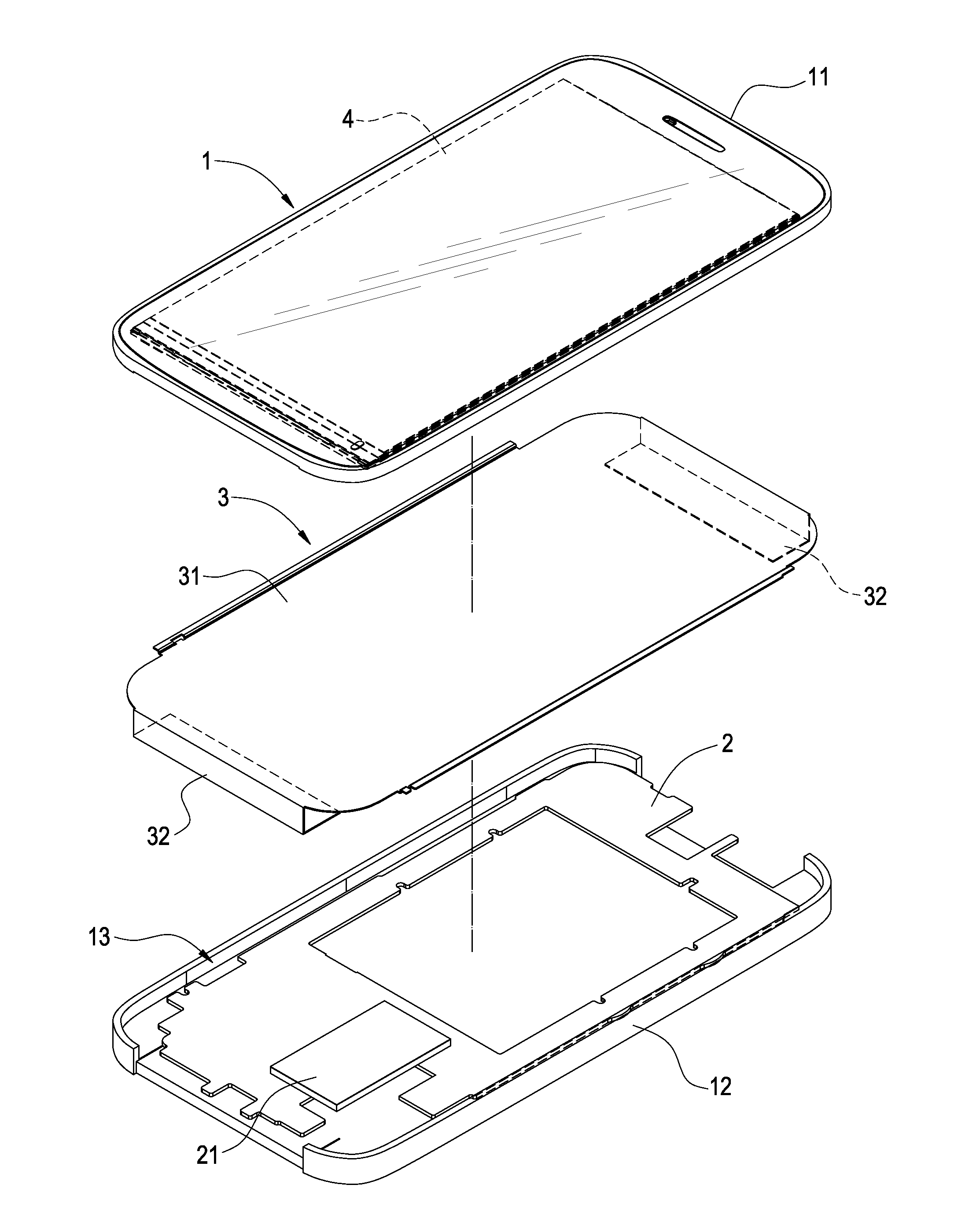
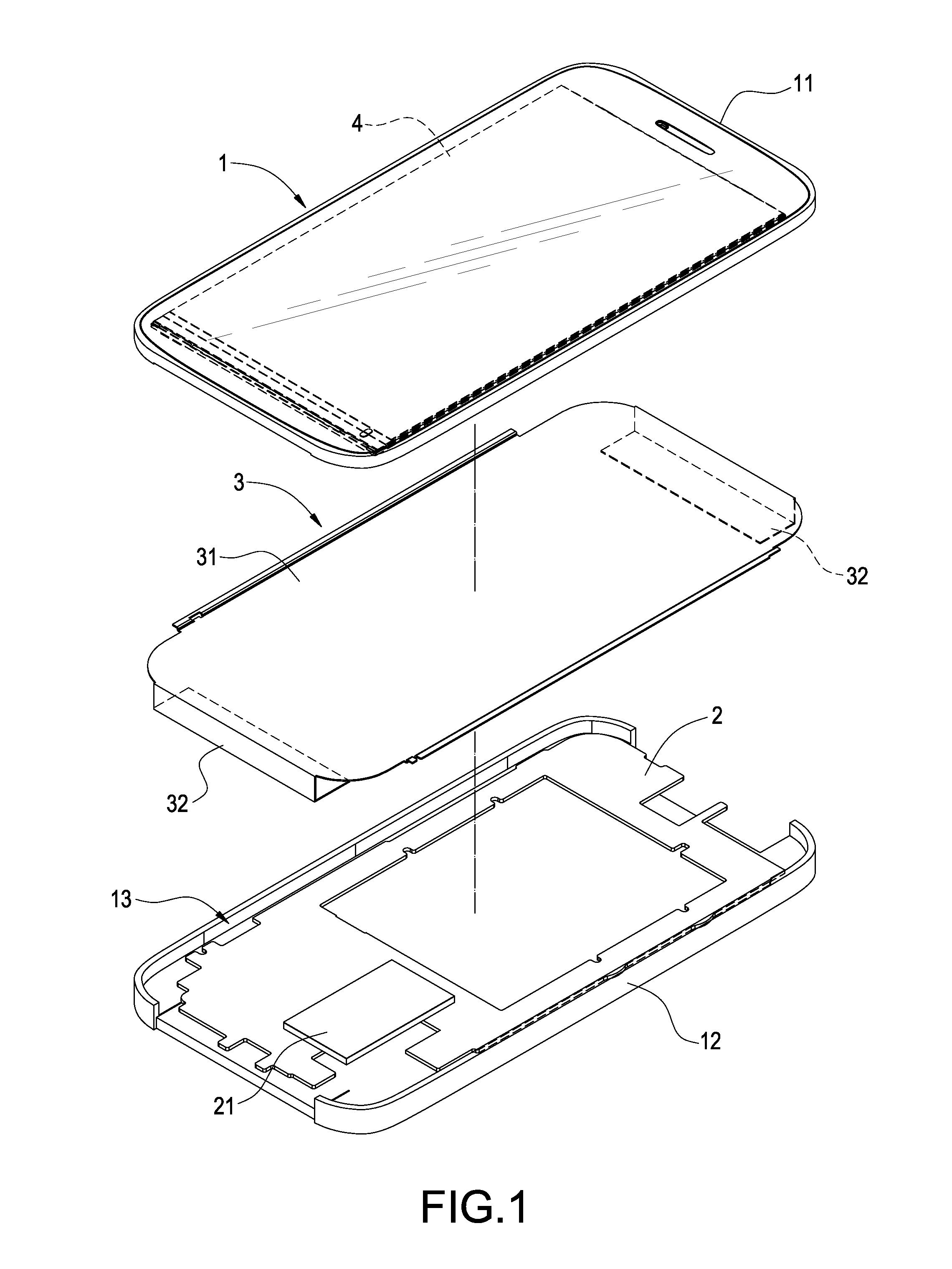
[0015]The present invention provides a portable electronic device with an exposed heat dissipating mechanism; wherein the portable electronic device can be a mobile phone, a personal digital assistant (PDA), an electronic reader or a tablet computer. As shown in FIG. 1, the portable electronic device of the present invention comprises: a housing 1, a circuit board 2 and a heat dissipating plate 3.

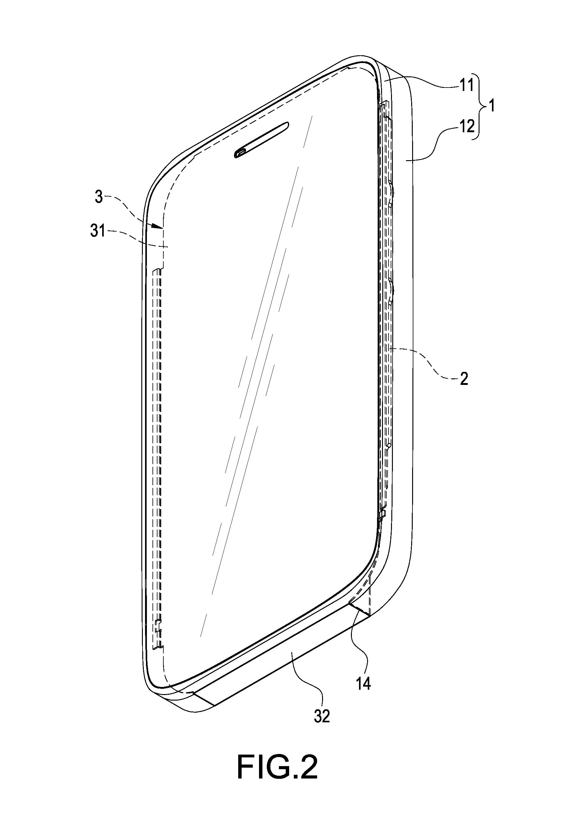
[0016]As shown in FIGS. 1-3, the housing 1 comprises an upper housing member 11 and a lower housing member 12. The upper housing member 11 and the lower housing member 12 can be attached to each other, and the assembled upper and lower housing members 11, 12 include a receiving space 13 formed there...


PUM


Abstract

A portable electronic device with an exposed heat dissipating mechanism includes a housing and a heat dissipating plate. A heat generating unit is arranged inside the housing, and the heat dissipating plate includes a main body arranged inside the housing and at least one cooling portion extended from the main body and exposed on the housing. The main body and the heat generating unit are thermally connected to each other. Therefore, the effectiveness of the heat dissipation can be enhanced without increasing the thickness of the device and such that the need for heat dissipation in a portable electronic device of higher performance and computing power can be satisfied.

Description

BACKGROUND OF THE INVENTION[0001]1. Field of the Invention[0002]The present invention is related to a portable electronic device, in particular, to a portable electronic device with an exposed heat dissipating mechanism[0003]2. Description of Related Art[0004]Portable electronic devices, including such as mobile phone, personal digital assistant (PDA), electronic reader and tablet computer, are developed to have greater performance with smaller sizes and thicknesses. As their performances advance with higher processing power, the heat generated by such portable devices also increases rapidly; in addition, due to the accumulation of the heat generated, the temperature at the internal environment of the portable electronic devices could increase to certain extend. As the time of usage of the device increases, the internal heat transferred out via the housing to the external of the device could even be felt by the user; furthermore, the continuous usages of the device along with the ac...

Claims


Application Information

Patent Timeline
Patent Type & Authority Applications(United States)
IPC IPC(8): G06F1/20
CPCG06F1/203H05K7/20154H05K7/20336H05K7/20409
Inventor YU, CHIA-HSINGWU, MING-CHIH
Owner CHAUN CHOUNG TECH
Learn More