Time synchronization system, management node, and time synchronization method

a time synchronization and management node technology, applied in the field of time synchronization systems, can solve the problems of inability to detect the switching of network paths, the accuracy of time synchronization for that duration,

Active Publication Date: 2014-11-27
HITACHI LTD
View PDF9 Cites 20 Cited by
  • Summary
  • Abstract
  • Description
  • Claims
  • Application Information

AI Technical Summary

Benefits of technology

[0023]An effect of the exemplary embodiment of the invention disclosed herein is summarized as follows. This invention enables to provide a time synchronization system that uses a plu...

Problems solved by technology

A problem of the method disclosed in JP 2009-077207 A is that, because the time slave needs to receive a time packet a plurality of times before detecting switching of network paths and cannot detect switching of network paths immediately after the switching, ...

Method used


Image

  • Time synchronization system, management node, and time synchronization method
  • Time synchronization system, management node, and time synchronization method
  • Time synchronization system, management node, and time synchronization method

Examples


first embodiment

[0046]A first embodiment of this invention is described below with reference to FIGS. 1 to 13.

[0047]A time synchronization system of this embodiment is a time synchronization system utilizing a wide area network that couples a plurality of bases to one another. The time synchronization system includes a management node for transmitting a network switching notification to a time slave when a network to which a time master transmits a time packet is switched to another network. This enables the time slave to quickly detect that networks have been switched.

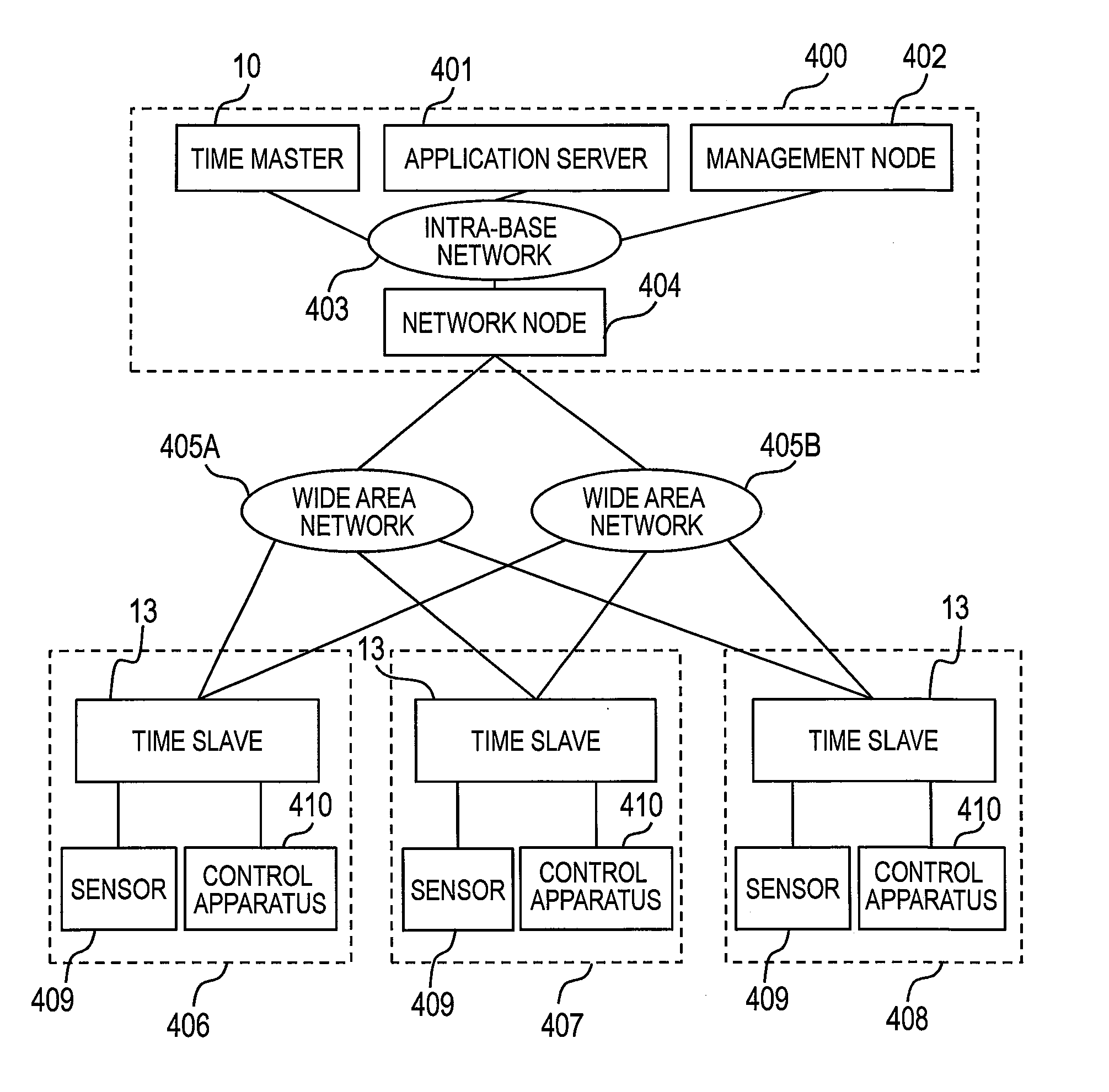
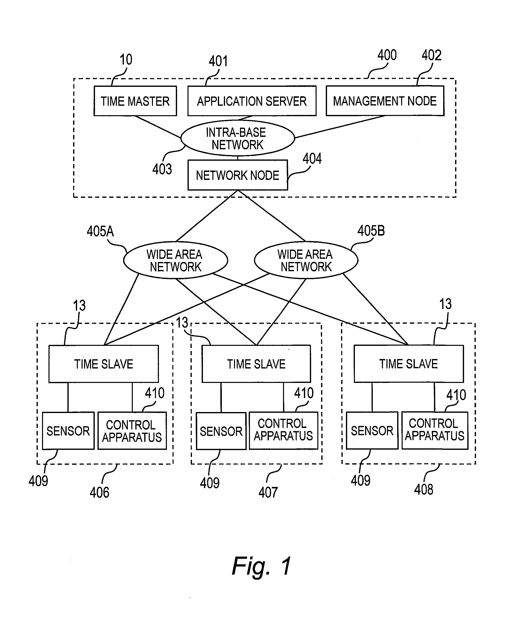
[0048]FIG. 1 is an explanatory diagram of the configuration of the time synchronization system according to the first embodiment of this invention.

[0049]In the time synchronization system, a control base 400 where a time master 10 is disposed is coupled to bases 406 to 408 where time slaves 13 are disposed by wide area networks 405A and 405B (hereinafter the wide area networks 405A and 405B are collectively referred to as wide area n...

second embodiment

[0153]A second embodiment of this invention is described below with reference to FIGS. 14 and 15.

[0154]In the first embodiment, a case where the time master 10 selects and uses one out of a plurality of wide area networks 405 to transmit a time packet has been described. Described in the second embodiment is the difference from the first embodiment of a case where the time master 10 selects and uses at least one out of a plurality of wide area networks 405 to transmit a time packet.

[0155]FIG. 14 is an explanatory diagram of the configuration of a time correcting part 1600 according to the second embodiment of this invention. Components of the time correcting part 1600 that are the same as those of the time correcting part 50 illustrated in FIG. 3 are denoted by the same reference symbols, and descriptions thereof are omitted.

[0156]The time correcting part 1600 of this embodiment differs from the time correcting part 50 of the first embodiment in that one time packet transmitting / rec...

third embodiment

[0162]A third embodiment of this invention is described below with reference to FIGS. 16 to 18.

[0163]In this embodiment, a network apparatus 181 is provided for each time slave 13 to be placed between the time slave 13 and the wide area networks 405. The difference of the third embodiment from the first embodiment is described below.

[0164]Each time slave 13 in the first embodiment has a communication interface and a packet transmitting / receiving part for each of the wide area networks 405 and the network that is coupled to the management node (the communication interfaces 601 to 603 and the packet transmitting / receiving part 604 to 606). In this embodiment, the network apparatus 181 converts three physical network interfaces into one network interface so that the time slave 13 only needs to have one communication interface 2001 illustrated in FIG. 18 and one packet transmitting / receiving part 2002 illustrated in FIG. 18.

[0165]FIG. 16 is an explanatory diagram of the configuration of...


PUM


Abstract

A time synchronization system comprises a time master, a time slave, and a management node which are coupled to one another via a plurality of networks. The time master transmits to the time slave a time packet at a given timing through at least one of the plurality of networks. The time slave has a time correcting part for receiving the time packet transmitted from the time master and for correcting time based on the received time packet. The management node has: a network switching determining part for determining whether to switch the network for transmitting a time packet to another of the plurality of networks; and a network switching notifying part for notifying, in a case where it is determined that the network for transmitting the time packet is to be switched, information for identifying the switched-to network to the time slave.

Description

INCORPORATE BY REFERENCE[0001]The present application claims priority from Japanese patent application JP 2011-287909 filed on Dec. 28, 2011, the content of which is hereby incorporated by reference into this application.BACKGROUND OF THE INVENTION[0002]This invention relates to a time synchronization system including a time master and a time slave, and more particularly, to a time synchronization system in which a time slave corrects time managed by the time slave itself based on a time packet transmitted from a time master.[0003]Application fields of information and telecommunication networks are expanding with the increase in the area and speed of information and telecommunication networks. Hitherto, systems that utilize a geographically limited information and telecommunication network have been built. Today, large-scale systems utilizing a wide area information and telecommunication network which is not geographically limited are being explored. A known example of such systems ...

Claims


Application Information

Patent Timeline
IPC IPC(8): H04J3/06H04L7/00H04L69/40
CPCH04J3/0676H04L7/0016H04J3/0658H04J3/0641H04J3/0667H04L69/40H04L69/28H04L67/125Y04S40/18
Inventor OGATA, YUJIYAMADA, MASAKI
Owner HITACHI LTD
Why Eureka
Try Eureka