Precise positioning actuator for head element, head gimbal assembly with the actuator and disk drive apparatus with the head gimbal assembly

a positioning actuator and head element technology, which is applied in the direction of maintaining the alignment of the head carrier, recording information storage, instruments, etc., can solve the problems of increasing the thickness of the hga around the magnetic head slider, only presenting enough accuracy for the position control of the magnetic head element with respect to the track in the magnetic disk, and easy shocks. the effect of improving the shock resistan

Inactive Publication Date: 2005-08-23
SAE MAGNETICS (HK) LTD
View PDF12 Cites 45 Cited by
  • Summary
  • Abstract
  • Description
  • Claims
  • Application Information

AI Technical Summary

Benefits of technology

[0015]It is therefore an object of the present invention to provide a precise positioning actuator for a head element, an HGA with the actuator and a disk drive apparatus with the HGA, whereby a shock resistance can be greatly improved.

Problems solved by technology

For advancing the track density, the position control of the magnetic head element with respect to the track in the magnetic disk by a voice coil motor (VCM) only has never presented enough accuracy.
However, an HGA with such piggy-back structure actuator will have following various problems:(1) Because of the stepwise stacked structure, a total thickness of the HGA around the magnetic head slider increases by the thickness of the actuator;(2) The actuator as a whole consists of piezoelectric material such as PZT of a brittle material, and the actuator and the magnetic head slider are stacked to form a cantilever structure.
A shock easily occurs with a moment and also shock resistance is very poor;(3) Depending upon the size of the magnetic head slider, a travel of the magnetic head element during the precise positioning operation varies.
Thus, it is difficult to obtain enough stroke;(4) Because of three-dimensional and complicated attachment structure of the actuator, the handling at the time of an assembly of the HGA is very difficult and it is impossible to use a conventional HGA assembly equipment causing productivity to be very worse; and(5) In order not to interfere with the movement of the actuator, it is necessary to assemble with keeping a gap between the actuator and the magnetic head slider and also between the actuator and the suspension.
However, forming of such gap will more decrease the shock resistance and it is difficult to precisely keep the gap constant.
Particularly, since it is difficult to keep the suspension, the actuator and the magnetic head slider in parallel precisely, the head characteristics deteriorates.
However, according to the actuator described in Japanese patent publication 2002074870A, since the slider fixing sections made of the same sintered ceramic were projected inwardly from the surfaces of the movable arms, stress due to applied shock concentrated to corners at the base of the projections causing these corners to be easily broken.
Thus, it was very difficult to greatly improve the shock resistance of the actuator.

Method used


Image

  • Precise positioning actuator for head element, head gimbal assembly with the actuator and disk drive apparatus with the head gimbal assembly
  • Precise positioning actuator for head element, head gimbal assembly with the actuator and disk drive apparatus with the head gimbal assembly
  • Precise positioning actuator for head element, head gimbal assembly with the actuator and disk drive apparatus with the head gimbal assembly

Examples


Embodiment Construction

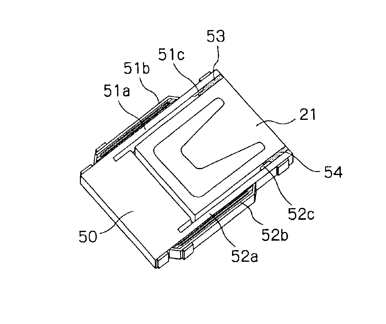
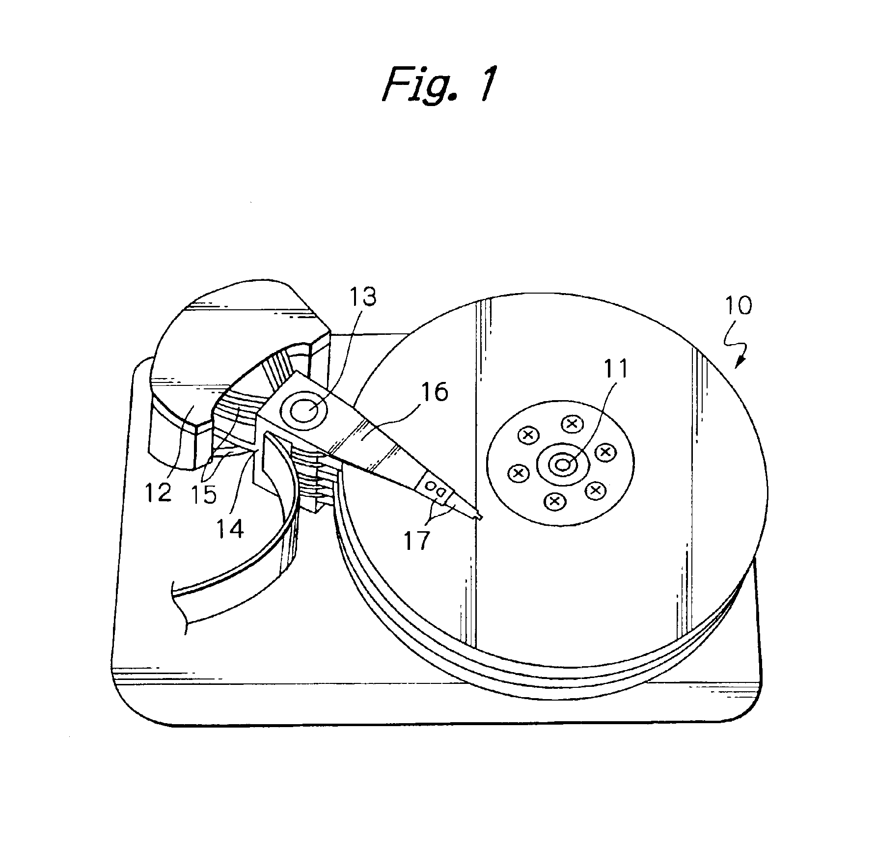
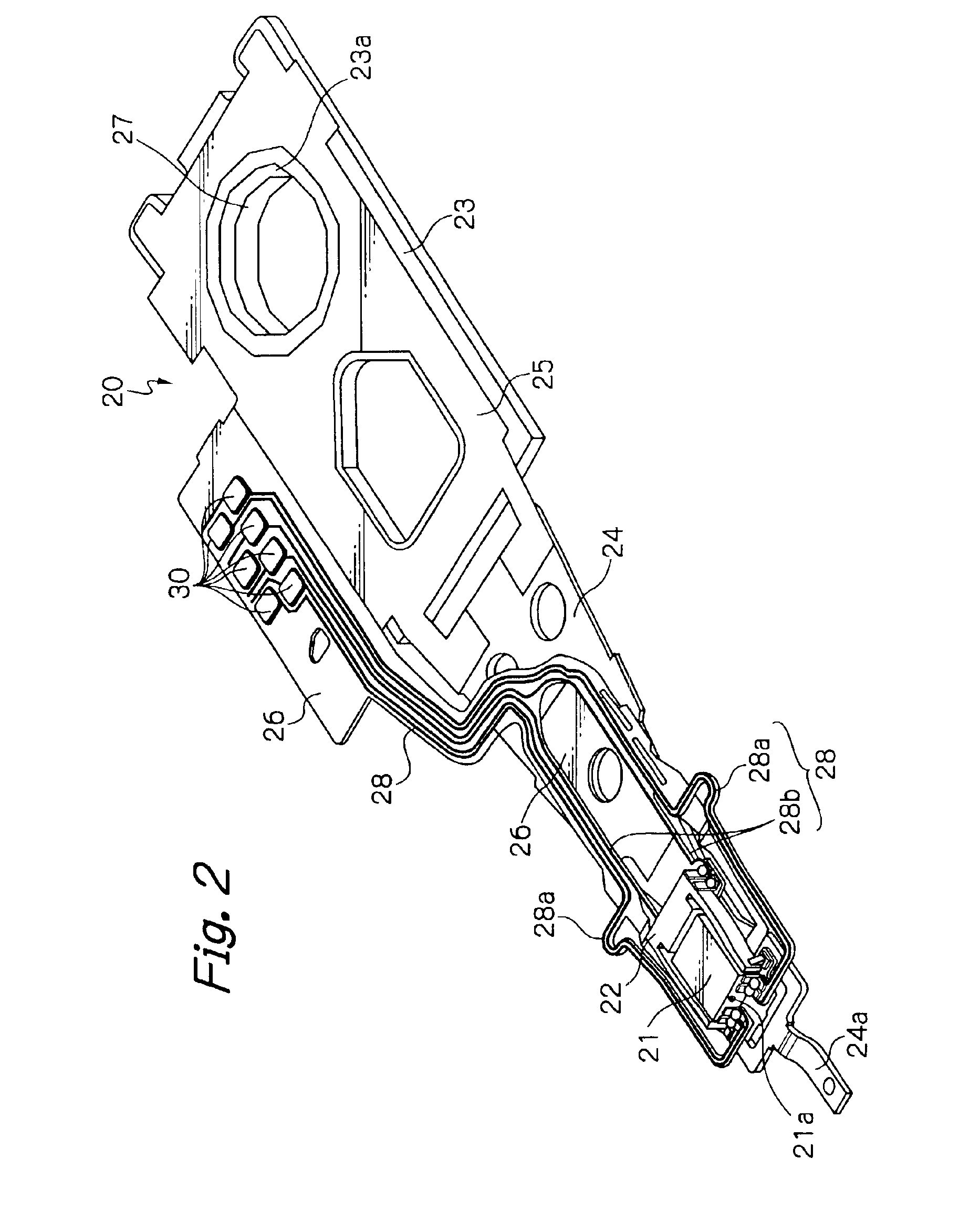
[0049]FIG. 1 illustrates main components of a magnetic disk unit of a preferred embodiment according to the present invention, FIG. 2 illustrates the whole structure of an HGA in this embodiment, and FIGS. 3 and 4 illustrate a top end section of the HGA in this embodiment, seen from different directions with each other.

[0050]In FIG. 1, reference numeral 10 denotes a plurality of magnetic hard disks rotating around an axis 11, and 12 denotes a housing of a voice coil motor (VCM) for positioning each magnetic head element on a track of each disk. The VCM housing 12 is mainly constituted by a carriage 14 capable of rotating around an axis 13 and a main actuator 15 such as the VCM for driving the carriage 14 to swing.

[0051]Base sections at one ends of a plurality of drive arms 16 stacked along the axis 13 are attached to the carriage 14, and one or two HGAs 17 are mounted on a top section at the other end of each arm 16. Each of the HGAs 17 has a slider mounted at its top end section so...


PUM

PropertyMeasurementUnit
thicknessaaaaaaaaaa
thicknessaaaaaaaaaa
thicknessaaaaaaaaaa

Abstract

A precise positioning actuator for precisely positioning at least one head element is provided with a base and a pair of movable arms capable of displacing in response to a drive signal applied to the actuator. The pair of movable arms extend from the base for catching a head slider with at least one head element in a space between the pair of movable arms. Each of the pair of movable arms includes an arm member made of an elastic sintered ceramic and having substantially the same cross sectional shape from a root thereof to a top end thereof, a piezoelectric element formed on a side surface of the arm member and a protrusion additionally formed on an inside surface of the arm member near its top end section. The protrusion has tapered surfaces. Side surfaces of the head slider are adhered to the inside surfaces of the arm members at the protrusions and within regions between the protrusions and top ends of the arm members.

Description

FIELD OF THE INVENTION[0001]The present invention relates to a precise positioning actuator for a head element such as a thin-film magnetic head element or an optical head element, to a head gimbal assembly (HGA), with the actuator and to a disk drive apparatus with the HGA.DESCRIPTION OF THE RELATED ART[0002]In a magnetic disk drive apparatus, thin-film magnetic head elements for writing magnetic information into and / or reading magnetic information from magnetic disks are in general formed on magnetic head sliders flying in operation above the rotating magnetic disks. The sliders are supported at top end sections of suspensions of HGAs, respectively.[0003]Recently, recording and reproducing density along the radial direction or along the track width direction in the magnetic disk (track density) rapidly increase to satisfy the requirement for ever increasing data storage capacities and densities in today's magnetic disk drive apparatus. For advancing the track density, the position...

Claims


Application Information

Patent Timeline
Patent Type & Authority Patents(United States)
IPC IPC(8): G11B5/55G11B5/596G11B5/58G11B21/10G11B21/21
CPCG11B5/5552
Inventor YAO, MING GAOSHIRAISHI, MASASHIKASAJIMA, TAMON
Owner SAE MAGNETICS (HK) LTD
Why Eureka
Try Eureka