
Wind turbine rotor blade having an electrical heating device and a plurality of lightning conductors

a technology of electrical heating device and wind turbine, which is applied in the direction of liquid fuel engines, vessel construction, marine propulsion, etc., can solve the problems of wind turbines being affected by lightning strikes, heating of heating devices, potential differences between lightning conductors and heating devices, and electrical conductors connected to heating devices. , to achieve the effect of preventing damage, simple configuration and effective equipotential bonding

Active Publication Date: 2014-11-27
NORDEX ENERGY SE & CO KG
View PDF5 Cites 25 Cited by
  • Summary
  • Abstract
  • Description
  • Claims
  • Application Information

AI Technical Summary

Benefits of technology

The invention relates to a wind turbine blade design that includes an electrical heating device to prevent damage caused by lightning strikes. The design uses a metallic conductor that runs over the entire length of the blade to create a continuous electrical connection between the blade and the heating device. This prevents damage to the blade caused by induced voltages and currents. The heating device can be supplied a heating current through the lightning conductors, and the conductors can be in electrical contact with the main spar cap of the blade. This design simplifies the connection between the heating device and the lightning conductors and eliminates the need for additional lightning conductors.

Problems solved by technology

As a result of their large physical height, wind turbines are often affected by lightning strikes.
These are made of an electrically conductive material and a heating current flows through them during operation; the heating current results in heating of the heating device.
On the basis of the Maxwell-Faraday equation, high voltages can be induced in the electrical heating device as a result, which results in potential differences between the lightning conductor and the heating device or between the lightning conductor and the electrical conductors connected to the heating device.
Depending on the current gradient and the geometric relationships in the rotor blade, these potential differences can amount to several megavolts, with the result that flashovers occur between the lightning conductor and the electrical heating device or the electrical conductors.
This can result in damage to the heating device or adjacent structures of the rotor blade, up to total damage.

Method used


Image

  • Wind turbine rotor blade having an electrical heating device and a plurality of lightning conductors
  • Wind turbine rotor blade having an electrical heating device and a plurality of lightning conductors
  • Wind turbine rotor blade having an electrical heating device and a plurality of lightning conductors

Examples


Embodiment Construction

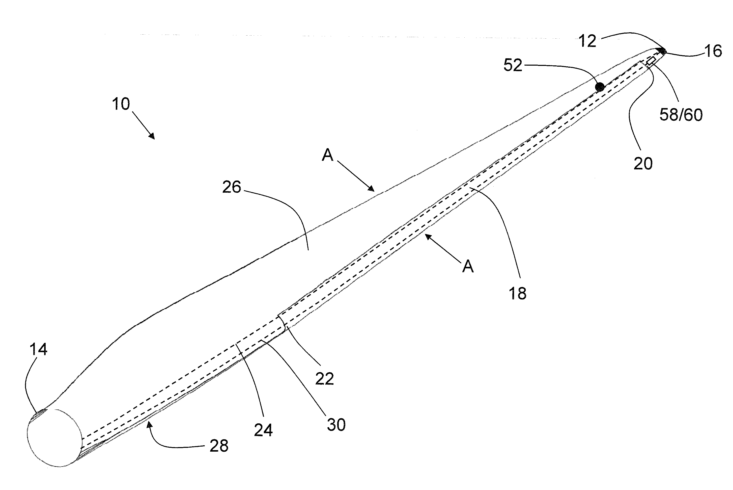
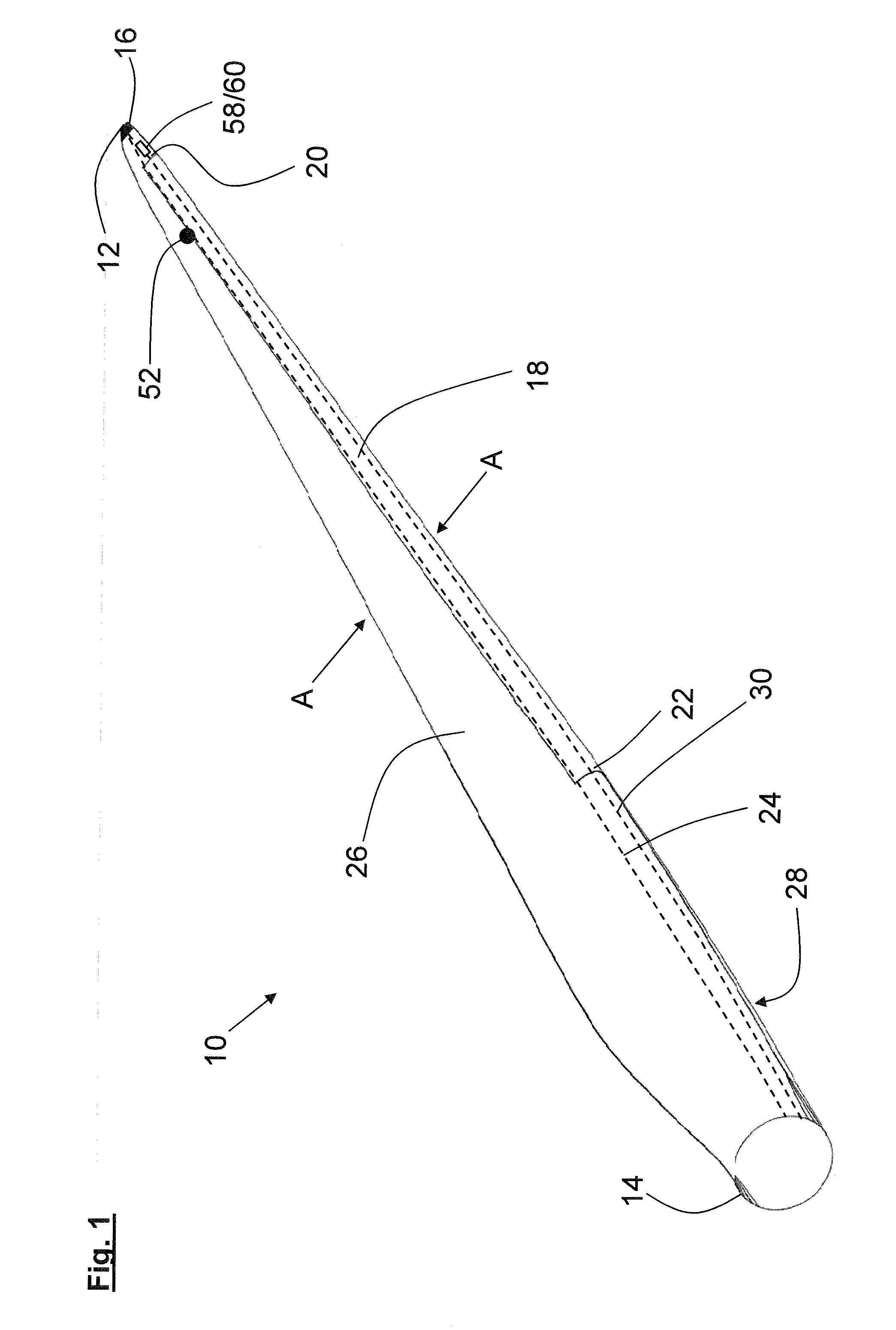
[0043]The wind turbine rotor blade 10 shown in FIG. 1 has a rotor blade tip 12 and a rotor blade root 14. A lightning protection receptor 16, which forms the rotor blade tip 12, is arranged in the region of the rotor blade tip 12. The rotor blade 10 has a pressure side 26 facing the viewer and a suction side 28 remote from the viewer.

[0044]An electrical heating device 18 is arranged in the region of the profile leading edge of the rotor blade 10. It has a rotor blade tip side end 20 and a rotor blade root side end 22 and extends over a large proportion of the length of the rotor blade 10 up to close to the rotor blade tip 12.

[0045]FIG. 1 also shows a first lightning conductor 24 which has a metallic conductor. The metallic conductor extends from the rotor blade root 14 up to the rotor blade tip 12 and is connected there to the lightning protection receptor 16. As shown in FIG. 1, the first lightning conductor 24 runs substantially adjacent to a rim of the electrical heating device 1...


PUM


Abstract

A wind turbine rotor blade includes: a rotor blade root; a rotor blade tip; an electrical heating device; a first lightning receptor disposed in the region of the rotor blade tip; precisely two lightning conductors leading from the lightning receptor to the rotor blade root; a second lightning receptor arranged at a distance to the rotor blade tip and connected to one of the lightning conductors; and, each one of the two lightning conductors being electrically conductively connected to the electrical heating device at a multiplicity of points between the rotor blade root and the rotor blade tip so as to cause equipotential bonding between the two lightning conductors via the electrical heating device in response to a lightning strike to the rotor blade.

Description

CROSS REFERENCE TO RELATED APPLICATION[0001]This application claims priority of European patent application no. 13002688.3, filed May 23, 2013, the entire content of which is incorporated herein by reference.FIELD OF THE INVENTION[0002]The invention relates to a wind turbine rotor blade having a rotor blade root, a rotor blade tip, an electrical heating device, a lightning receptor in the region of the rotor blade tip and a plurality of lightning conductors leading from the lightning receptor to the rotor blade root.BACKGROUND OF THE INVENTION[0003]As a result of their large physical height, wind turbines are often affected by lightning strikes. Most frequently, the lightning strikes in the region of the rotor blade tip when the rotor blade is pointing upwards at an angle or straight. In order to prevent destruction of the rotor blade by the lightning strike, it has long been known to arrange a lightning receptor in the region of the rotor blade tip and to connect it to a lightning ...

Claims


Application Information

Patent Timeline
IPC IPC(8): F03D11/00
CPCF03D11/0033F03D11/0025F03D80/30F03D80/40Y02E10/72
Inventor KLEIN, HENDRIK
Owner NORDEX ENERGY SE & CO KG
Learn More