
Bipolar battery assembly

a battery and bipolar technology, applied in the field of bipolar battery assembly, can solve the problems of cell and battery non-functionality, and the seal of the electrochemical cell to rupture, so as to prevent electrical shorting and prevent electrical shorting

Active Publication Date: 2014-11-27
ADVANCED BATTERY CONCEPTS
View PDF6 Cites 76 Cited by
  • Summary
  • Abstract
  • Description
  • Claims
  • Application Information

AI Technical Summary

Benefits of technology

The patent describes a new design for batteries that can be used in various environments. These batteries are designed to handle the pressure and heat generated during operation without getting damaged. They can be easily assembled and adapted to different shapes and sizes. The design allows for efficient assembly and can withstand high levels of pressure without getting damaged.

Problems solved by technology

Despite the advantages of bipolar battery assemblies, the disadvantages of bipolar battery assemblies have prevented them from being commercialized.
In addition, the heat evolved can exacerbate the pressures generated and can result in runaway reactions which can generate heat levels that damage the materials of construction of the batteries and render the batteries non-functional.
The pressures can cause the seals about the electrochemical cell to rupture and render the cells and battery nonfunctional.
Present and future users of batteries often have limited packaging space available for batteries and batteries that can be adapted to available packaging space are needed.

Method used


Image

  • Bipolar battery assembly
  • Bipolar battery assembly
  • Bipolar battery assembly

Examples


example 1

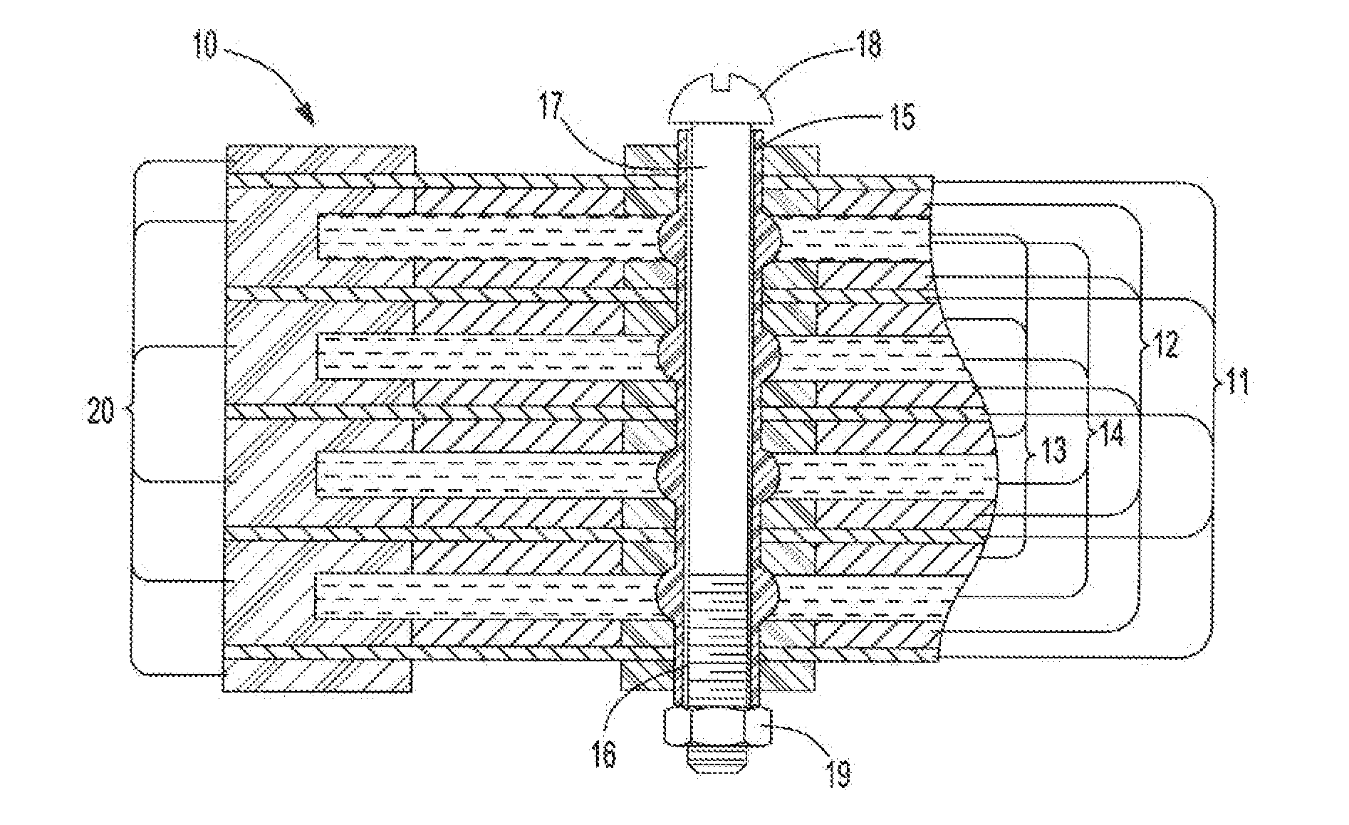
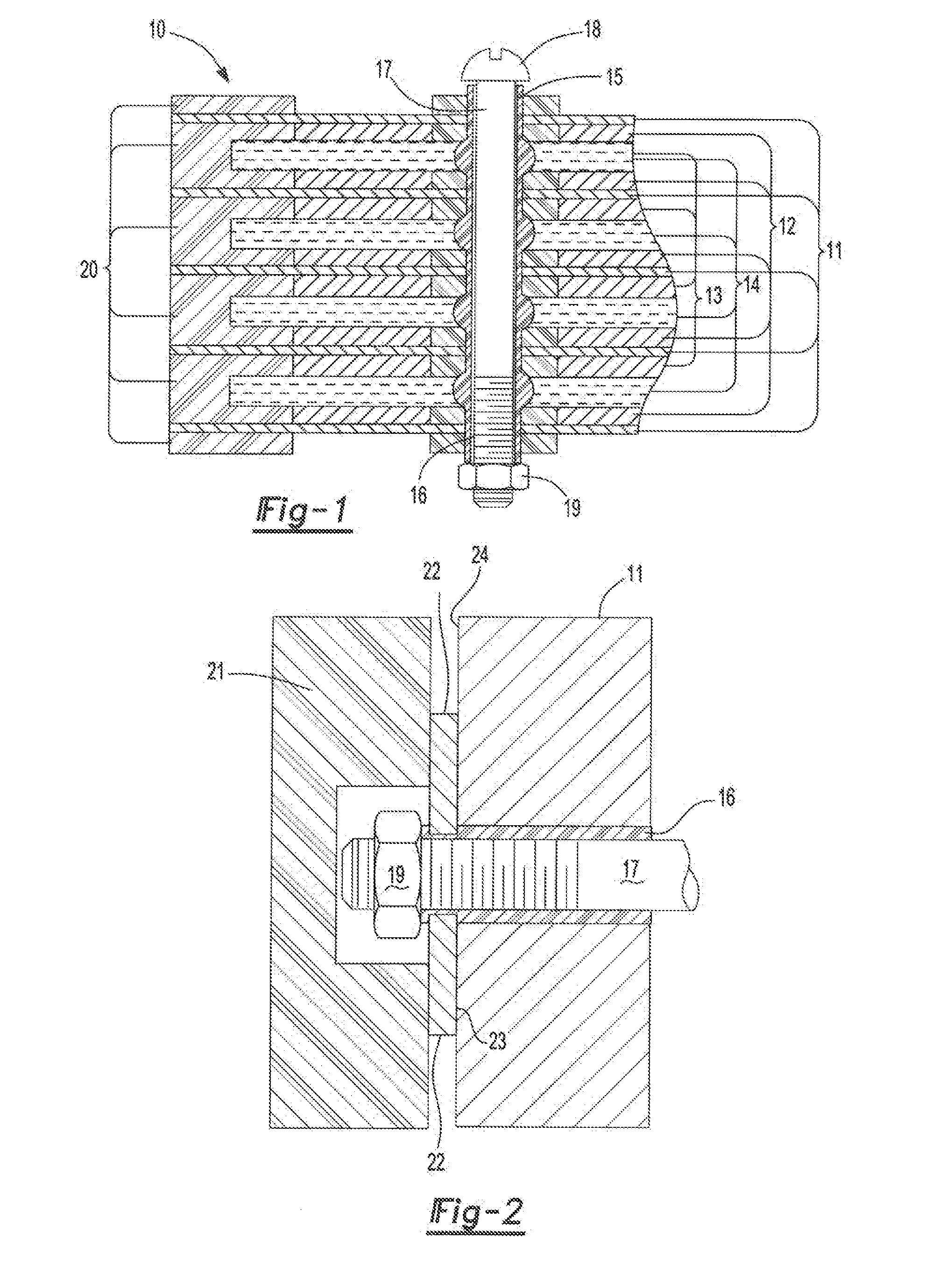
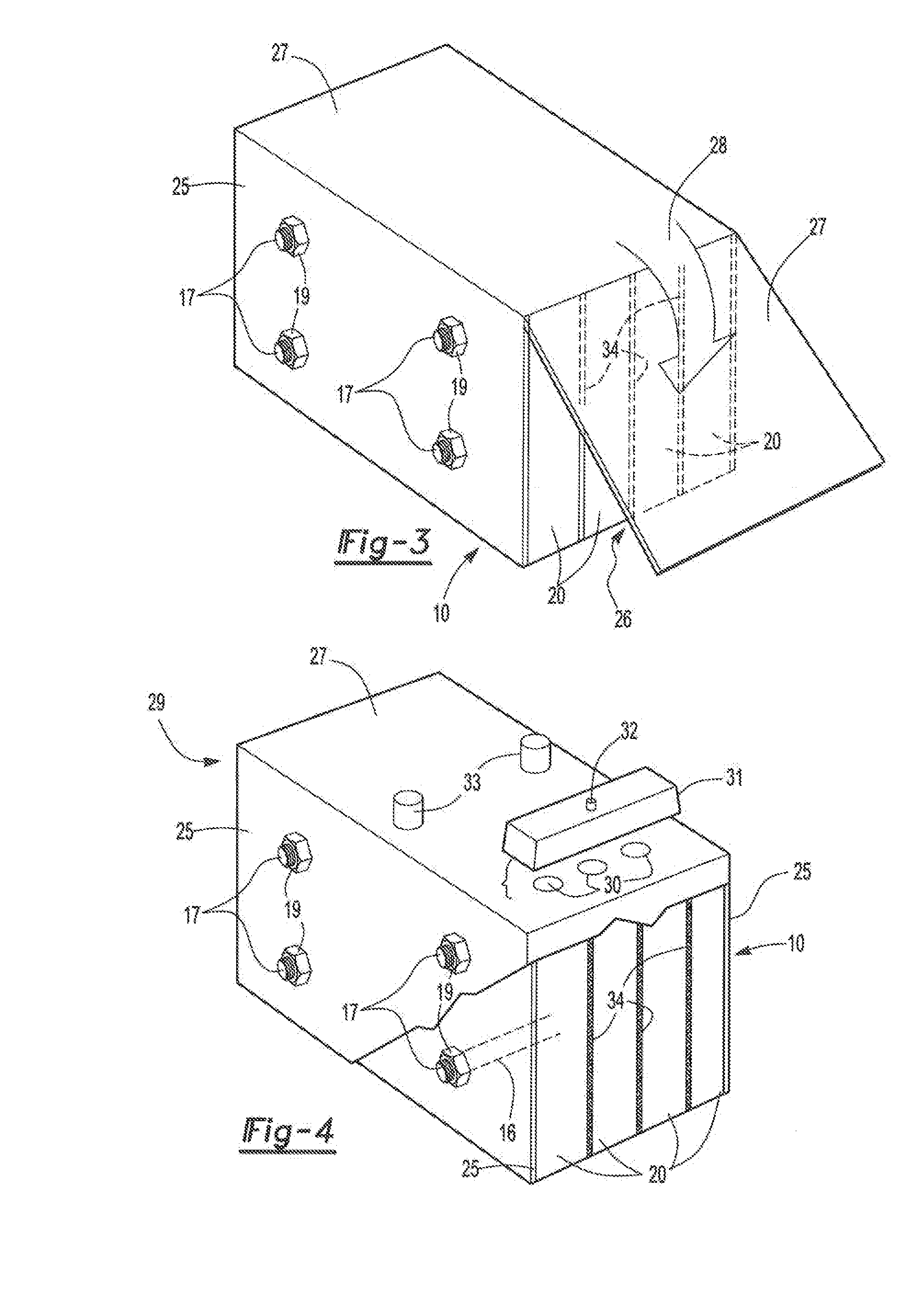
[0058]A 12V bipolar battery is built using two monopole plates (positive and negative) and 5 bipolar plates. The plates are manufactured using methods as described herein and Commonly owned patent application titled BIPOLAR BATTERY ASSEMBLY, Shaffer I I, et al. US 2010 / 0183920. In this example the plates are 197 mm by 173 mm and include four transverse channel holes. The plates are pasted using standard lead-acid active materials for the negative active material and positive active material. The battery is assembled by stacking onto four rods through the transverse channels. This ensures alignment of the plates. After each plate is placed four bushings are dropped onto the alignment rods. These bushings will establish the final compressed height of the separator. Absorbent glass mat separator is then stacked such that holes are cut into the separator to accommodate the bushings. This process is repeated for all of the cells. The assembly is compressed and secured with temporary bolt...

example 2

[0062]A second battery is built similar to Example 1. In this example the transverse channels are filled with an epoxy resin. A cap feature is molded on the ends of the resin on the end plate to assist in supporting the compressive load. After assembly the battery is pressure tested with helium at 4 psi while immersed in a water tank. No visible leaks are observed. As before the battery is filled with acid and formed. The battery exhibits an OCV of 12.93V, a 20 hour discharge capacity of 17.8 amp hour (Ah) and a resistance of 24 milliohms.

example 3

[0063]A 96 volt battery is built using similar methods described in Example 1. The battery is built with a positive monopolar end assembly, a negative monopolar end assembly and 47 bipolar plates. In this example the transverse channels are tapped and a threaded plastic rod is inserted into the channels. The threaded rod extends past the monopole end plates. Similar to Example 1 the threaded rod is heat-staked to form the end-seal and secure compressive loads. After assembly the battery is pressure tested with 4 psi of helium, no leaks are observed. As before the battery is filled with acid and formed. The battery exhibits an OCV of 103.5V and a 20 hour capacity of 17 Ah.


PUM

PropertyMeasurementUnit
pressuresaaaaaaaaaa
diameteraaaaaaaaaa
diameteraaaaaaaaaa

Abstract

The invention relates to an article comprising: a) one or more stacks of battery plates comprising one or more bipolar plates; b) located between each plate is a separator and a liquid electrolyte; further comprising one of more of the features: 1) c) the one or more stacks of battery plates having a plurality of channels passing transversely though the portion of the plates having the cathode and / or the anode deposited thereon; and d) i) one or more seals about the periphery of the channels which prevent the leakage of the liquid electrolyte into the channels, and / or posts located in one or more of the channels having on each end an overlapping portion that covers the channel and sealing surface on the outside of the monopolar plates adjacent to the holes for the transverse channels and applies pressure on the sealing surface of the monopolar plates wherein the pressure is sufficient to withstand pressures created during assembly and operation of electrochemical cells created by the stacks of battery plates; 2) c) a membrane comprising a thermoplastic polymer is disposed about the entire periphery of the edges of the stack of plates; 3) wherein the separator is in the form of a sheet having adhered to its periphery a frame; and 4) c) an integrated valve and integrated channel communicating with the valve.

Description

[0001]This application claims the benefit of the filing date of U.S. Provisional Application No. 61 / 550,657, filed on Oct. 24, 2011, the contents of which are incorporated by reference herein for all purposes.FIELD[0002]The present invention relates generally to a bipolar battery assembly, to methods for the preparation of such assemblies and to methods of using such assemblies.BACKGROUND[0003]Bipolar batteries are known in the art, see Tatematsu US 2009 / 0042099, incorporated herein by reference in its entirety. Bipolar batteries provide advantages over other battery designs such as scalability, relatively high energy density, high power density and design flexibility. Bipolar batteries comprise a number of bipolar plates and two monopolar end plates. A bipolar plate comprises a substrate which is in the form of a two sided sheet having a cathodic material, often referred to a Positive Active Material (PAM), on one surface and on the opposite side is an anodic material, often referr...

Claims


Application Information

Patent Timeline
Patent Type & Authority Applications(United States)
IPC IPC(8): H01M4/14H01M10/14H01M10/18H01M2/12H01M50/121H01M50/528
CPCH01M4/14H01M2/1223H01M10/14H01M2300/0011H01M2004/029H01M2220/20H01M10/18H01M6/48H01M8/248H01M10/0418H01M10/044H01M10/282H01M10/0468H01M4/668Y02E60/10H01M50/30H01M50/24H01M50/317H01M50/581H01M50/121H01M10/0525Y02E60/50Y02P70/50H01M50/20
Inventor SHAFFER, II, EDWARD O.HOBDAY, DONALD
Owner ADVANCED BATTERY CONCEPTS
Learn More