Self-powered energy harvesting switch and method for harvesting energy

Inactive Publication Date: 2014-12-04
SIGNIFY HLDG BV
View PDF8 Cites 44 Cited by
  • Summary
  • Abstract
  • Description
  • Claims
  • Application Information

AI Technical Summary

Benefits of technology

[0005]An object of the present invention is to provide a wireless switch device which is simple for the user to operate

Problems solved by technology

But usually, in order to provide energy, switch devices are battery-operated, with lifetime dependent on power supply, and replacement of batteries is required, usually

Method used


Image

  • Self-powered energy harvesting switch and method for harvesting energy
  • Self-powered energy harvesting switch and method for harvesting energy
  • Self-powered energy harvesting switch and method for harvesting energy

Examples


first embodiment

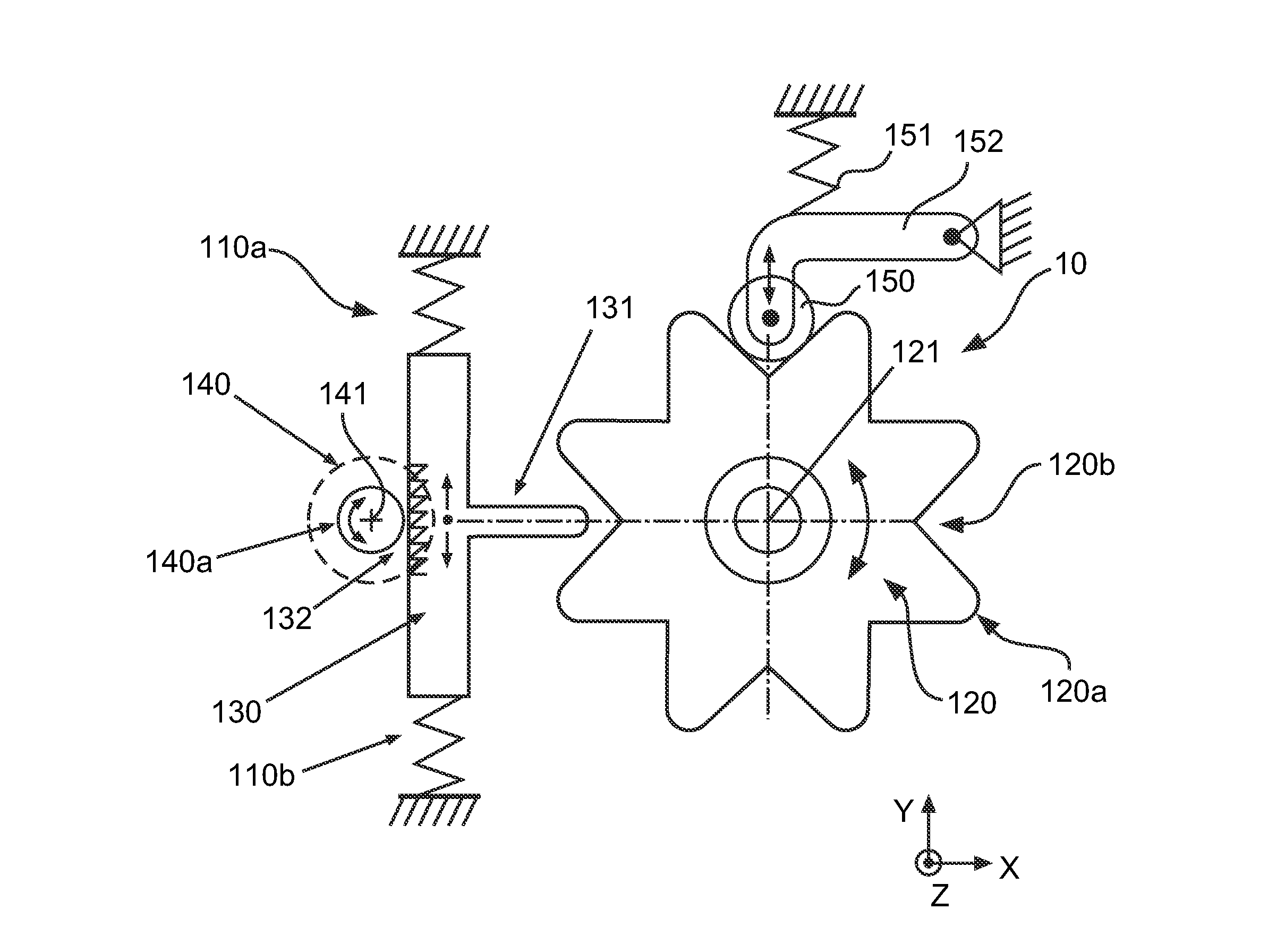
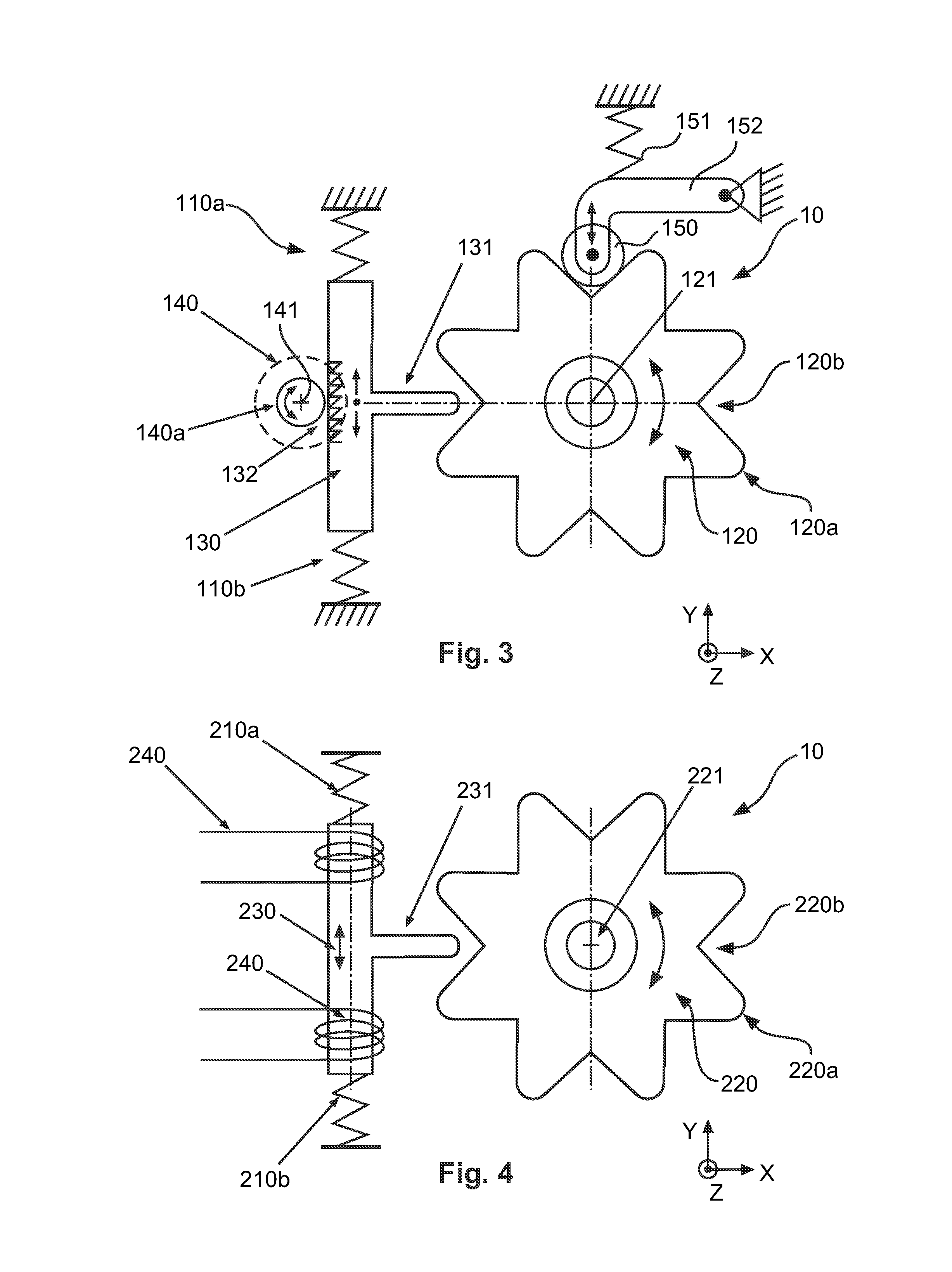
[0044]FIG. 3 shows a drive unit 120 provided in the form of a gear wheel with recess portions 120b and protruding portions 120a. This gear wheel shown as 120 in FIG. 3 is also shown in FIG. 1 as drive unit 20. In particular, there are provided eight protruding portions 120a and eight recess portions 120b between the protruding portions 120a. It is not necessary to have eight protruding portions also more or less protruding portions is possible. The gear wheel 120 can be actuated around a rotation axis 121 by a force, e.g. a user, especially in both rotational directions, and in particular by an actuation device, as can be seen in FIG. 1, interacting with the drive unit 120. A moving device 130 is provided in the form of a block with a protrusion 131 protruding from the block in an x-direction towards the drive unit 120 into one of the recess portions 120b. The moving device 130 is arranged such that the protrusion 131 rests in a zero position with respect to an y-axis facing in a d...

second embodiment

[0047]FIG. 4 basically shows a drive unit with a configuration like the one shown in FIG. 3, but there is a difference with respect to the energy harvester. FIG. 4 shows a drive unit 220 provided in the form of a gear wheel with recess portions 220b and protruding portions 220a. In particular, there are provided eight protruding portions 220a and eight recess portions 220b between the protruding portions 220a. The gear wheel 220 can be actuated around a rotation axis 221 by a force, e.g. by a user, especially in both rotational directions, and in particular by an actuation device (not shown) interacting with the drive unit 220. A moving device 230 is provided in the form of a magnetic block with a protrusion 231 protruding from the magnetic block in an x-direction towards the drive unit 220 and engaging in one of the recess portions 220b. The moving device 230 is arranged such that the protrusion 231 rests in a zero position with respect to a y-axis facing in a directing in which t...

third embodiment

[0049]FIG. 5 shows a drive unit 320 which is provided in the form of a kind of gear wheel with recess portions 320b and protruding portions 320a. In particular, by means of example, there are provided three protruding portions 320a and three recess portions 320b between the protruding portions 320a. The protruding portions 320a themselves have protruding elements 322, further protruding in a radial direction away from a rotation axis 321 of the drive unit 320 and provided in order to engage with a moving device 230. The drive unit 320 can be actuated around the rotation axis 321 by a force, e.g. by a user, especially in both rotational directions, and in particular by an actuation device (not shown) interacting with the drive unit 320. A moving device 330 is provided in the form of a kind of wheel with a plurality of protrusions 331 protruding in a radial direction from the rotation axis 332 of the moving device 330. In contrast to the embodiments shown in FIGS. 3 and 5, the protru...


PUM


Abstract

A switch device (10) and method for generation of energy for operating the switch device (10), wherein the switch device (10) is provided with a drive unit (120) interacting with an actuation device operable by a user, and with a moving device (130) configured to be set in motion by the drive unit (120), and with an energy harvester (132, 140, 140a) for providing energy to the switch device (10) in dependence on a motion of the moving device (130), such that energy for commands or other operations is provided to the switch device (10). The moving device (130) is configured to be repeatedly repositioned in relation to a defined zero position, as long as it has kinetic energy, in order to provide kinetic energy which can be converted in electric energy by the energy harvester (132, 140, 140a). Such an electromechanical device for generating energy can ensure wireless operation of the switch device (10) without the need of batteries or any other kind of power supply.

Description

FIELD OF THE INVENTION[0001]The present invention relates to a self-powered switch device and a method of generating energy, especially energy required for operation and communication and interaction with an operator.BACKGROUND OF THE INVENTION[0002]Wireless switches, remote controls, sensors, energy control devices or the like which are self-powered provide the advantage of device positioning independently of specific energy supply situations like cables or power outlets. The installation locations can be chosen and determined regardless of any power supply constraints, and even portable respectively mobile control and sensing devices can be provided. But usually, in order to provide energy, switch devices are battery-operated, with lifetime dependent on power supply, and replacement of batteries is required, usually after an uncertain time period. Such replacement operations implicate time-consuming and laborious and costly installation work, depending on the location of each swit...

Claims


Application Information

Patent Timeline
IPC IPC(8): H01H25/06
CPCH01H2300/052H01H25/06H01H2239/076H01H2300/032H02K7/1876H02K7/1892H02K35/00H02K2201/18Y02B90/20Y04S20/14
Inventor ERDMANN, BOZENAVAN DER HORST, ADRIANUS JOHANNES JOSEPHUSVAN ES, ARTHUR ROBERTDE WIT, BAS WILLIBRORDLELKENS, ARMAND MICHEL MARIETOLHUIZEN, LUDOVICUS MARINUS GERARDUS MARIA
Owner SIGNIFY HLDG BV
Why Eureka
Try Eureka