
Method of manufacture a sliding bearing

a technology of sliding bearings and sliding plates, which is applied in the direction of refractive reflectors, mechanical devices, optical elements, etc., can solve the problems of high hard particulate concentration, difficult production of composite layers with such high concentration, and significant wear during the start-up phas

Inactive Publication Date: 2014-12-04
MAHLE INT GMBH +1
View PDF5 Cites 1 Cited by
  • Summary
  • Abstract
  • Description
  • Claims
  • Application Information

AI Technical Summary

Benefits of technology

The patent describes a method for making a sliding bearing by depositing a layer of hard particles embedded in a metallic matrix on a substrate. The process involves using a repeating cycle of bias pulses to create the layer, with each cycle consisting of a high cathodic bias portion and a low cathodic bias portion, a zero cathodic bias portion, and an anodic bias portion. The method can also involve agitating the electrolyte to maintain the hard particles in suspension. The bearing can be used in engines, and the high cathodic bias portion can have a peak current density of 0.5 to 10 A / dm2. The method can result in a layer that is highly uniform and has improved properties such as hardness and strength.

Problems solved by technology

A particular challenge to bearing overlay layer performance is provided by the configuration of vehicle engines to save fuel by using a stop-start operation, in which the engine is stopped each time the vehicle stops, in contrast to conventional engine operation, in which the engine is kept running throughout a vehicle's journey.
The particular problem that an engine configured for stop-start operation presents arises because engine bearings are conventionally hydrodynamically lubricated, with little or no lubrication initially being provided to the bearings when the engine starts, leading to particularly significant wear during the start-up phase.
However, the production of such composite layers, with a high concentration of hard particulate, is difficult by conventional electroplating techniques, particularly in a tin-based alloy matrix (e.g. at least 50% wt tin), and most particularly in the case of a pure tin matrix.

Method used


Image

  • Method of manufacture a sliding bearing
  • Method of manufacture a sliding bearing
  • Method of manufacture a sliding bearing

Examples


Embodiment Construction

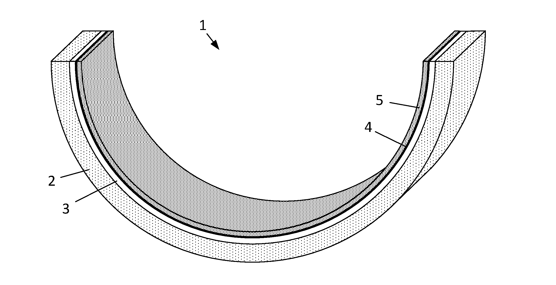
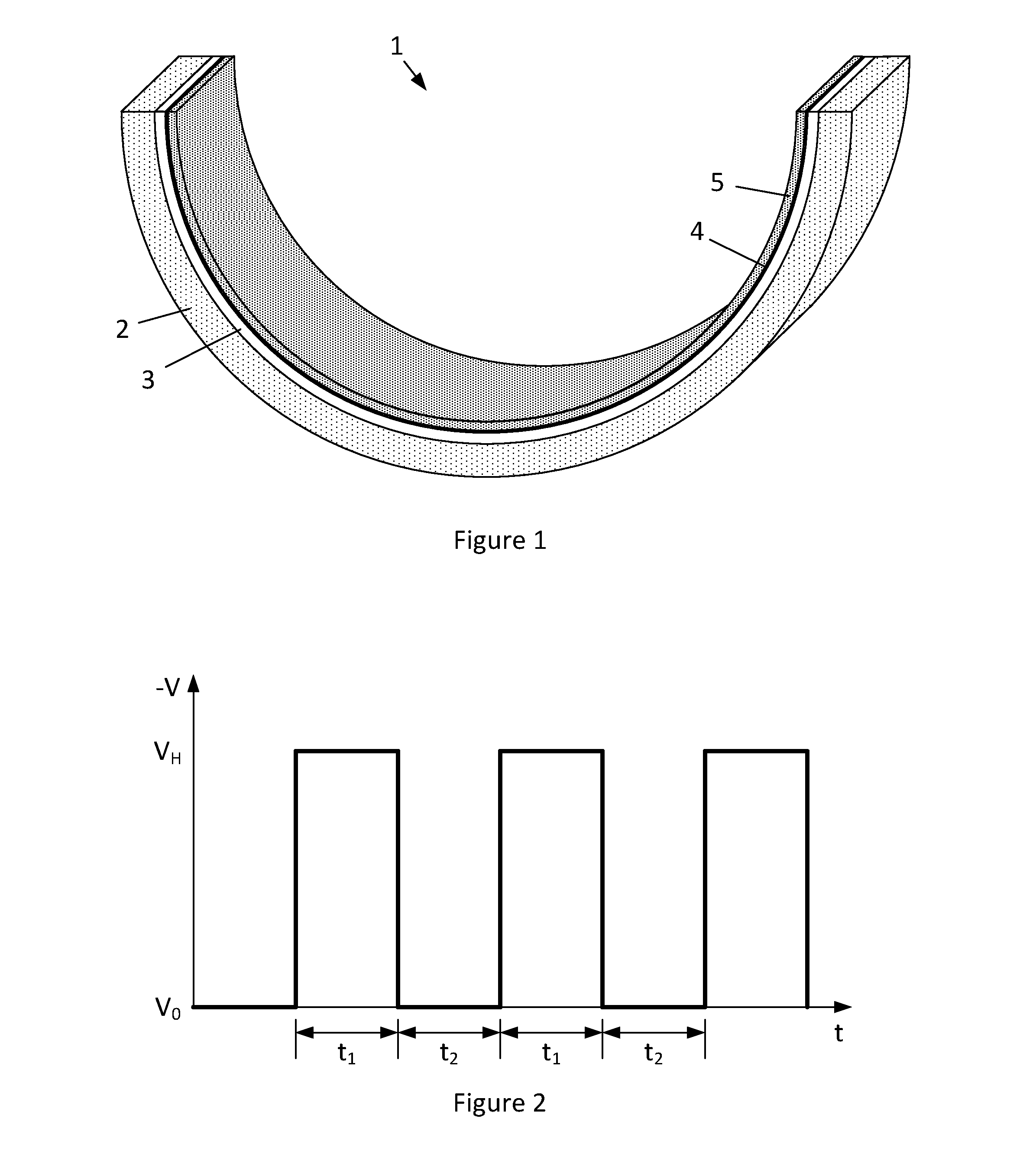
[0035]FIG. 1 illustrates a hollow generally semi-cylindrical bearing shell 1 having a steel backing layer 2, a copper-based alloy lining layer 3, a nickel or cobalt diffusion barrier 4, and a composite overlay layer 5 of hard particulate incorporated into a Sn matrix.

[0036]The bearing shell onto which the composite layer is deposited is provided as a cathode in a bath containing a suspension of hard particulate in an electroplating electrolyte, with an anode formed of a material corresponding to the metallic matrix, e.g. a high purity tin anode.

[0037]The electrolyte is a lead-free, tin methanesulfonic acid (MSA) electrolyte (tin ions in methanesulfonic acid), which may comprise performance enhancing additives, such as brightener and anti-foaming agent. For example the electrolyte may be the Bright Tin GBF 30 acidic electrolyte system from Schlötter® Galvanotechnik, which uses a recipe of Schlötter's ingredients consisting of 13.0 litres Tin Concentrate FS 20 (which contains 310 g / l ...


PUM

PropertyMeasurementUnit
peak current densityaaaaaaaaaa
cathodic current densityaaaaaaaaaa
concentrationsaaaaaaaaaa

Abstract

A method of manufacturing a sliding bearing comprising providing a substrate as a cathode in an electrolyte within which a hard particulate is suspended, and depositing a composite layer of hard particulate embedded in a metallic matrix by applying a repeating cycle of bias pulses to the substrate wherein each cycle comprises a high cathodic bias portion and a further bias portion selected from the group consisting of a low cathodic bias portion, a zero cathodic bias portion and an anodic bias portion, and a sliding bearing manufactured by such a method.

Description

[0001]The present invention relates to a method of electroplating a sliding bearing with a composite layer of hard particulate incorporated in a metallic matrix, and more particularly, but not exclusively, to bearing shells and thrust washers.BACKGROUND[0002]Bearing shells for journaled engine bearings typically comprises a strong steel backing layer, a lining layer and an overlay layer that provides the running surface for the journaled shaft, e.g. a hollow generally semi-cylindrical steel backing layer, a copper-based alloy lining layer, and a tin, tin-based alloy or composite overlay layer on the inner surface.[0003]It is desirable to provide increased wear resistance and to improve the fatigue strength of layers in bearing linings, particularly overlay layers. A particular challenge to bearing overlay layer performance is provided by the configuration of vehicle engines to save fuel by using a stop-start operation, in which the engine is stopped each time the vehicle stops, in c...

Claims


Application Information

Patent Timeline
Patent Type & Authority Applications(United States)
IPC IPC(8): C25D15/00
CPCC25D15/00C25D5/18C25D7/10C25D21/12
Inventor KACHOOSANGI, ROOHOLLAHCAREY, JOHNHANSAL, WOLFGANGHANSAL, SELMAQORRI, GENTIANA
Owner MAHLE INT GMBH
Learn More