
MRI acoustic system, acoustic output device, and electro-acoustic transducer

Active Publication Date: 2014-12-04
SAMSUNG ELECTRONICS CO LTD
View PDF2 Cites 8 Cited by
  • Summary
  • Abstract
  • Description
  • Claims
  • Application Information

AI Technical Summary

Benefits of technology

The patent describes an MRI system that uses an acoustic system to help with image quality. A filter is used to prevent interference between the MRI machine and the loudspeakers. The system also uses a current to reduce the magnetic field generated by the MRI machine. The number of turns in the coil is also determined to achieve the desired magnetic field. Overall, this technology helps improve MRI image quality and provides better audio experiences for patients.

Problems solved by technology

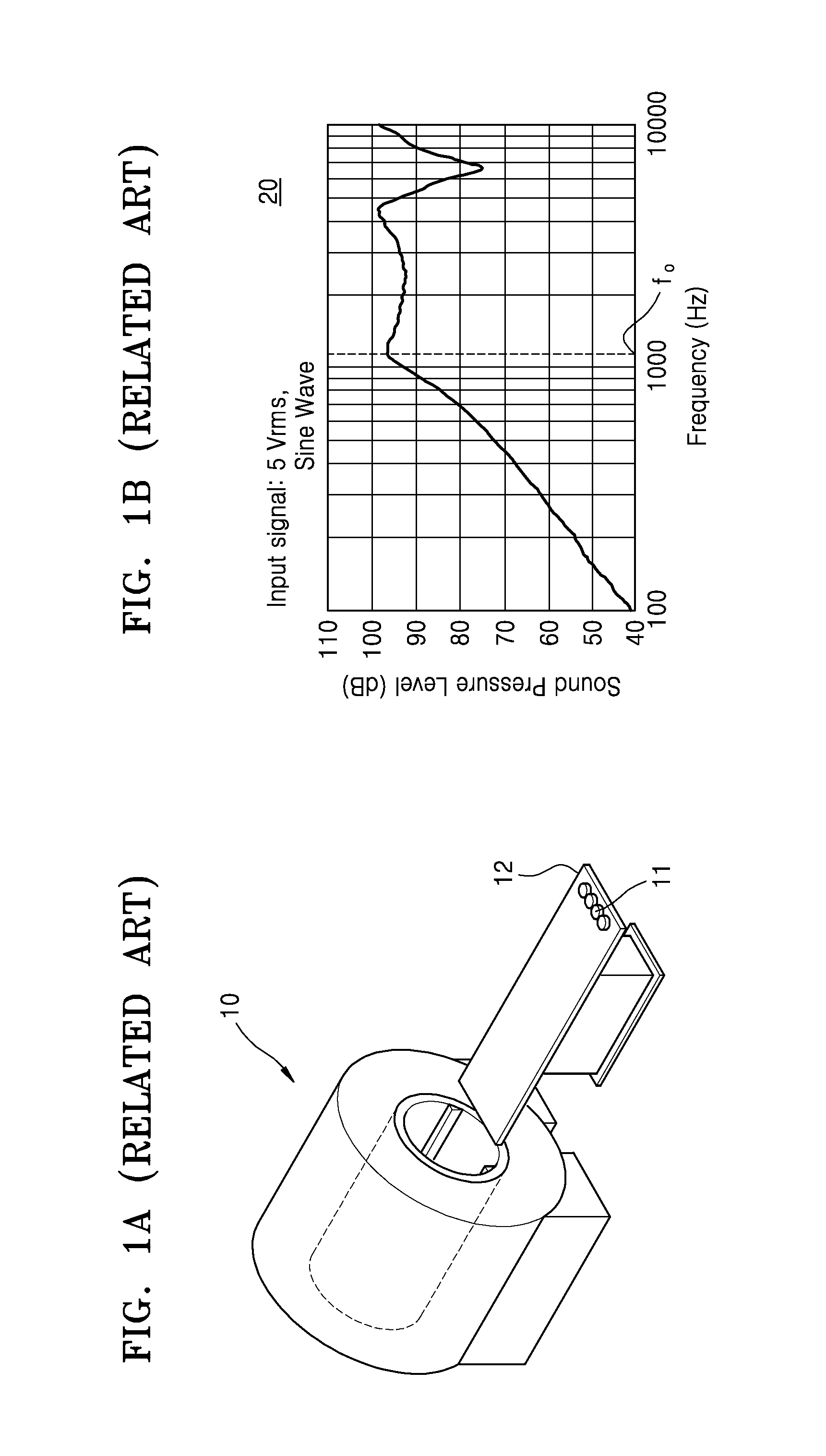
However, a magnetic material in the loud speaker may affect the magnetic field of the MRI apparatus, and the piezo-electric speaker has a limited number of frequency bands for sound output and is expensive.
Also, the exemplary embodiments are not required to overcome the disadvantages described above, and an exemplary embodiment may not overcome any of the problems described above.

Method used


Image

  • MRI acoustic system, acoustic output device, and electro-acoustic transducer
  • MRI acoustic system, acoustic output device, and electro-acoustic transducer
  • MRI acoustic system, acoustic output device, and electro-acoustic transducer

Examples


Embodiment Construction

[0085]Below, certain exemplary embodiments are described in greater detail with reference to the accompanying drawings.

[0086]In the following description, like reference numerals are used for the like elements, even in different drawings. The matters defined in the description, such as detailed construction and elements, are provided to assist in a comprehensive understanding of exemplary embodiments. However, exemplary embodiments can be carried out without those specifically defined matters. Also, well-known functions or constructions are not described in detail since that would obscure the description with unnecessary detail.

[0087]The terms used herein may vary according to the intention of one of ordinary skill in the art, the precedent, or the emergence of new technologies. It should be understood that “comprises,”“comprising,”“includes,” and / or “including” means an inclusion of other additional elements.

[0088]An “object” may include a person or a thing to be inspected, or may ...


PUM


Abstract

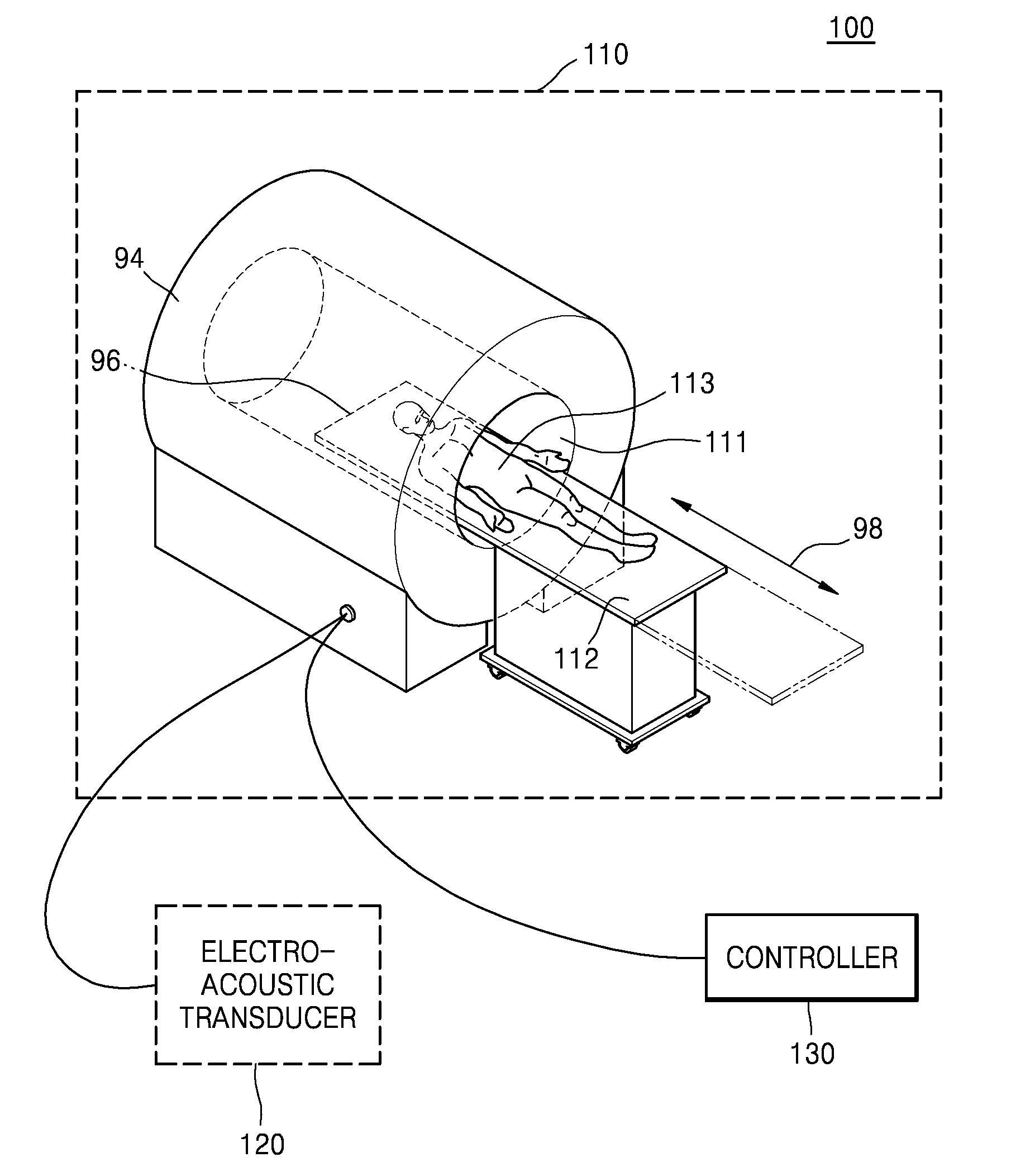
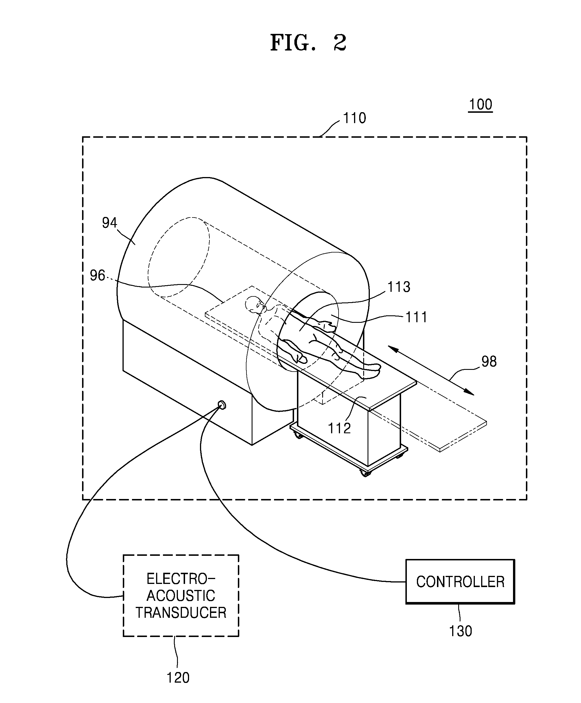
Provided is magnetic resonance imaging (MRI) acoustic system that includes a magnet that is included in a bore having an image-taking space where an object is able to be accommodated and that forms a magnetic field in the image-taking space to obtain an MR image of the object, an electro-acoustic transducer that is located outside of the bore, and includes coils through which a current for generating an attraction force or a repulsion force with respect to the magnetic field generated by the magnet and a vibrating plate that vibrates in response to the an attraction force or the repulsion force, and a controller that controls the intensity of the current inputted to the electro-acoustic transducer to generate a sound by using the magnetic field that is generated by the magnet.

Description

CROSS-REFERENCE TO RELATED PATENT APPLICATION[0001]This application is a continuation-in-part application of U.S. application Ser. No. 13 / 863,637, which claims the priority from Korean Patent Application No. 10-2012-0118671, filed on Oct. 24, 2012, in the Korean Intellectual Property Office, the disclosure of which is incorporated herein in its entirety by reference.BACKGROUND[0002]1. Field[0003]Methods and apparatuses consistent with exemplary embodiments relate to a magnetic resonance imaging (MRI) acoustic system, and more particularly, to an MRI acoustic system including an acoustic output device and an electro-acoustic transducer that operate based on a magnetic field of the MRI acoustic system.[0004]2. Description of the Related Art[0005]A magnetic resonance (MR) image is obtained through magnetic resonance of an atomic nucleus in a magnetic field. Resonance of an atomic nucleus is a phenomenon where the atomic nucleus in a lower energy state changes to a higher energy state b...

Claims


Application Information

Patent Timeline
IPC IPC(8): G01R33/28G01R33/383G01R33/54
CPCG01R33/283A61B5/055G01R33/383G01R33/543A61B5/704
Inventor KWON, OH-SOO
Owner SAMSUNG ELECTRONICS CO LTD
Learn More