Light scanning apparatus, light scanning control apparatus, and light scanning unit

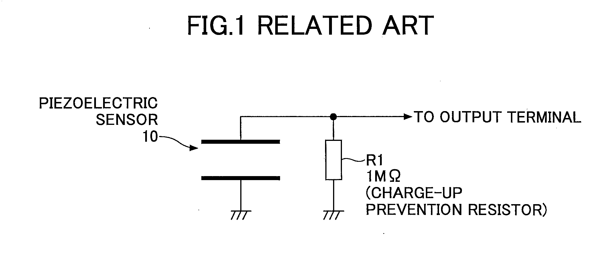
a control apparatus and light scanning technology, applied in the direction of optics, instruments, optics, etc., can solve the problems of exemplary piezoelectric sensors that are prone to noise and the sensitivity of mirror displacement with passage of time, and achieve the effect of preventing charge-up

Active Publication Date: 2014-12-04
MITSUMI ELECTRIC CO LTD
View PDF8 Cites 7 Cited by
  • Summary
  • Abstract
  • Description
  • Claims
  • Application Information

AI Technical Summary

Benefits of technology

[0008]FIG. 1 illustrates a connection of an exemplary piezoelectric sensor. One electrode of the exemplary piezoelectric sensor 10 is grounded, and the other electrode of the exemplary pi

Problems solved by technology

In the exemplary piezoelectric sensor, a great drop of the output voltage is possibly caused by aging degradation to thereby make sensitivity to the displacement of the mirror unresponsive

Method used


Image

  • Light scanning apparatus, light scanning control apparatus, and light scanning unit
  • Light scanning apparatus, light scanning control apparatus, and light scanning unit
  • Light scanning apparatus, light scanning control apparatus, and light scanning unit

Examples


first embodiment

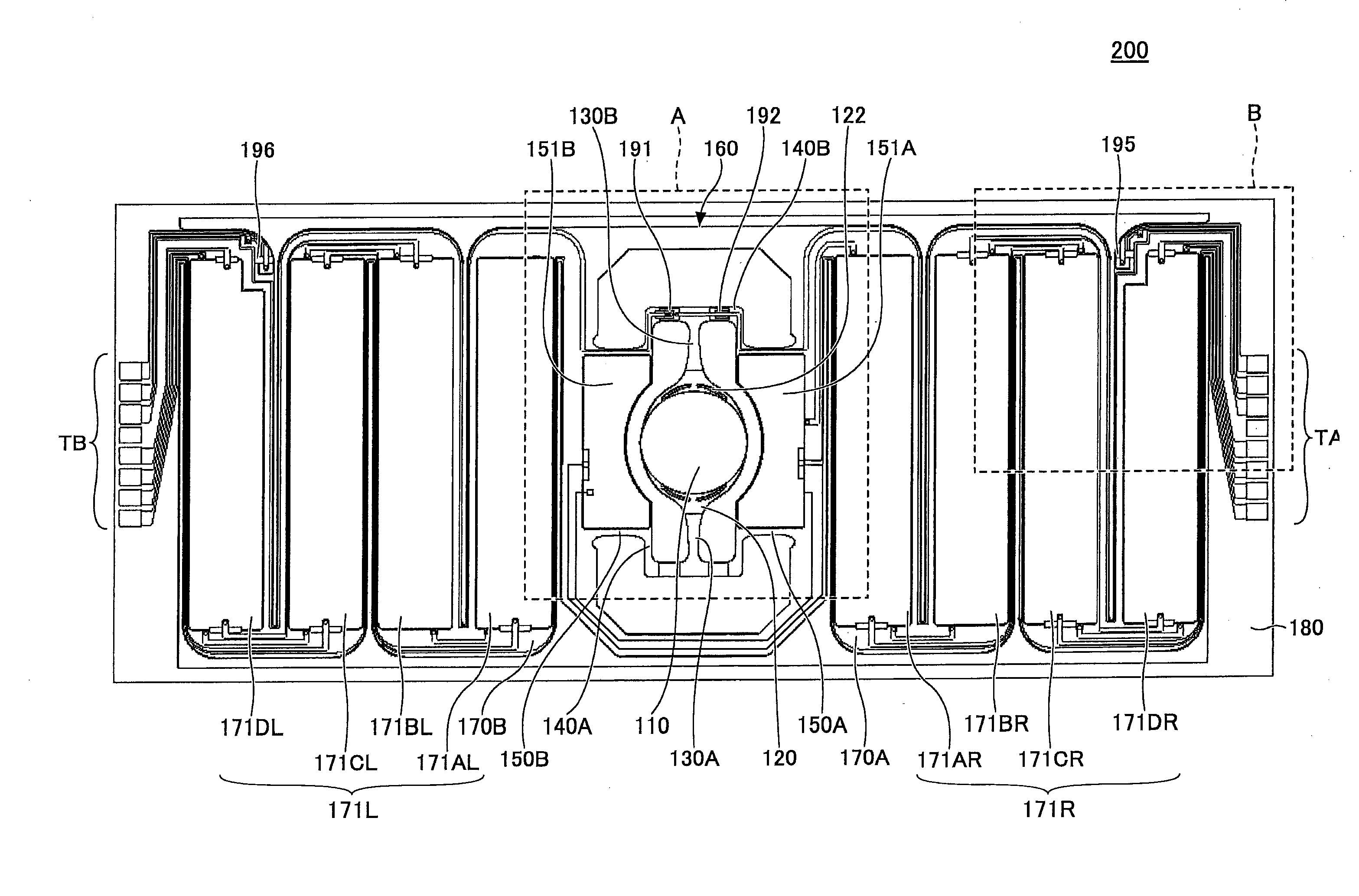
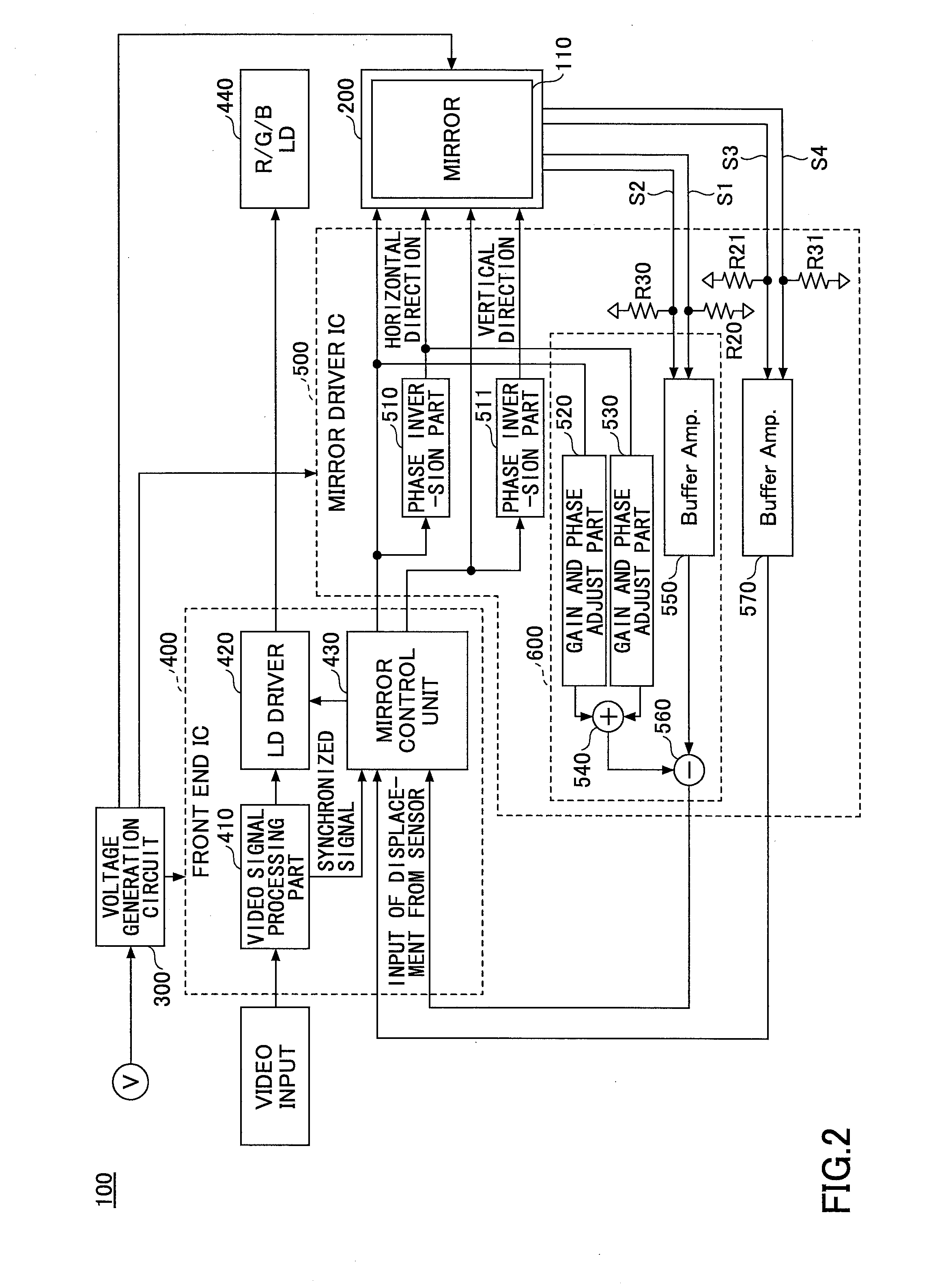
[0035]FIG. 2 illustrates a light scanning unit of a first embodiment of the present invention.

[0036]The light scanning unit 100 of the first embodiment includes a light scanning apparatus 200, a voltage generation circuit 300, a front end integrated circuit (IC) 400, a laser diode (LD) 440, a mirror driver IC 500, and resistors R20, R21, R30, and R31.

[0037]The light scanning apparatus 200 of the embodiment is a light scanning apparatus 200 causing a light emitted from the LD 440 to scan. The light scanning apparatus 200 is a micro electro mechanical system (MEMS) mirror or the like where a mirror is driven by, for example, a piezoelectric element or the like.

[0038]The light scanning unit 100 of the first embodiment includes a light scanning apparatus 200. The voltage generation circuit 300, the front end integrated circuit (IC) 400, the LD 440, the mirror driver IC 500, and the resistors R20, R21, R30, and R31 form a light scanning control apparatus for controlling the light scannin...

second embodiment

[0112]Next, a second embodiment of the present invention is described with reference to figures. The second embodiment is different from the first embodiment at a point that the resistor for generating the bias voltage is connected between the light scanning apparatus 200 and a mirror driver IC 500A. Within the second embodiment, only parts different from the first embodiment are described. Reference symbols are used for the same parts as those of the first embodiment, and description of these parts are omitted.

[0113]FIG. 9 illustrates a light scanning unit of the second embodiment of the present invention.

[0114]The light scanning unit 100A includes a mirror driver IC 500A. The mirror driver IC 500A of the second embodiment is different from the mirror driver IC 500 at a point that the resistors R20, R30, R21, and R31 are not included.

[0115]The resistors R20, R30, R21, and R31 are connected between the light scanning apparatus 100 and the mirror driver IC 500A.

[0116]Specifically, on...

third embodiment

[0119]Next, a third embodiment of the present invention is described in reference of figures. The third embodiment is different from the first embodiment at a point that the resistor for generating the bias voltage and the buffer for amplifying the sensor signal are provided between the light scanning apparatus 200 and a mirror driver IC 500B. Within the third embodiment, only parts different from the first embodiment are described. Reference symbols are used for the same parts as those of the first embodiment, and description of these parts are omitted.

[0120]FIG. 10 illustrates a light scanning unit of the third embodiment of the present invention.

[0121]The light scanning unit 100B includes the mirror driver IC 500B. The mirror driver IC 500B of the third embodiment is different from the mirror driver IC 500 at a point that the buffers 550 and 570 and the resistors R20, R30, R21, and R31 are not included.

[0122]In the light scanning unit 100B, the wires S1 and S2 are connected with ...


PUM


Abstract

A light scanning apparatus includes torsion beams supporting a mirror supporting portion on opposite sides of the mirror supporting portion along an axis direction, the mirror supporting portion being swung around the axis direction by the torsion beams; a pair of drive beams sandwiching the mirror and the mirror supporting portion in a direction orthogonal to the axis direction; connection beams that connect mutually facing sides of each drive beam with the torsion beams; and a piezoelectric sensor formed on the connection beams and detecting displacement of the connection beams caused by a swing of the torsion beams around the axis when the mirror swings by a drive voltage, wherein a first bias voltage having a positive or negative polarity is applied to an upper electrode of the piezoelectric sensor, and a second bias voltage having an opposite polarity is applied to a lower electrode.

Description

CROSS-REFERENCE TO RELATED APPLICATIONS[0001]This patent application is based upon and claims the benefit of priority of Japanese Patent Application No. 2013-116689 filed on Jun. 3, 2013, the entire contents of which are incorporated herein by reference.BACKGROUND OF THE INVENTION[0002]1. Field of the Invention[0003]The embodiments of the present invention relate to a light scanning apparatus that causes a mirror supporting portion, which is supports a mirror and is supported by a torsion beam on both sides of an axis, to swing in directions around the axis by torsion of the torsion beam, a light scanning control apparatus for controlling the light scanning apparatus, and a light scanning unit including the light scanning apparatus and the light scanning control apparatus.[0004]2. Description of the Related Art[0005]In an example of a light scanning apparatus disclosed in, for example, Japanese Laid-open Patent Publication No. 2012-208352, a mirror portion for reflecting an incident...

Claims


Application Information

Patent Timeline
IPC IPC(8): G02B26/10
CPCG02B26/105
Inventor HIBIYA, RIICHIROSEKINE, HISAMICHI
Owner MITSUMI ELECTRIC CO LTD
Why Eureka
Try Eureka