Fast transient precision power regulation apparatus

Active Publication Date: 2014-12-04
TEXAS INSTR INC
View PDF9 Cites 11 Cited by
  • Summary
  • Abstract
  • Description
  • Claims
  • Application Information

AI Technical Summary

Benefits of technology

[0008]Apparatus disclosed herein implement a fast transient precision current limiter such as may be included in an electronic voltage regulator. The current limiter includes two current sense element/current clamp control loops. A fast response time control loop first engages and clamps a current spike. A precision control loop then engages to more accurately clamp the output current to a programmed set point.
[0009]Each of the control loops includes a current sense element coupled to a voltage regulation control input. Voltage regulation control circuitry senses the over-current condition as a voltage drop at the voltage regulator output terminals. The voltage regulation control circuitry responds by increasing the magnitude of a voltage regulation control drive signal to a pass element through which current from the voltage regulator flows to the load. Thus, large increases in the voltage reg

Problems solved by technology

However, sense transistor-based current clamps tra

Method used


Image

  • Fast transient precision power regulation apparatus
  • Fast transient precision power regulation apparatus
  • Fast transient precision power regulation apparatus

Examples


Embodiment Construction

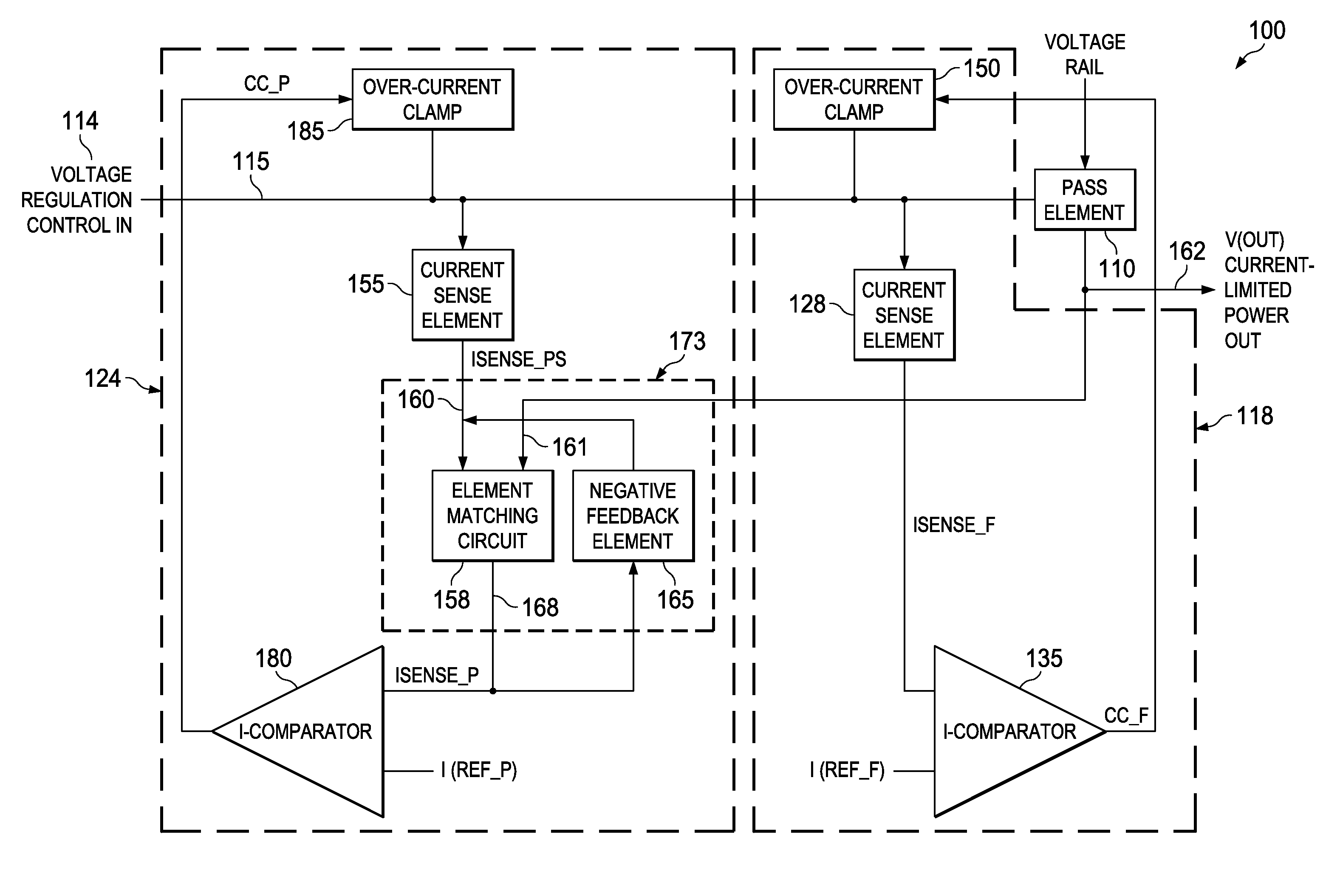
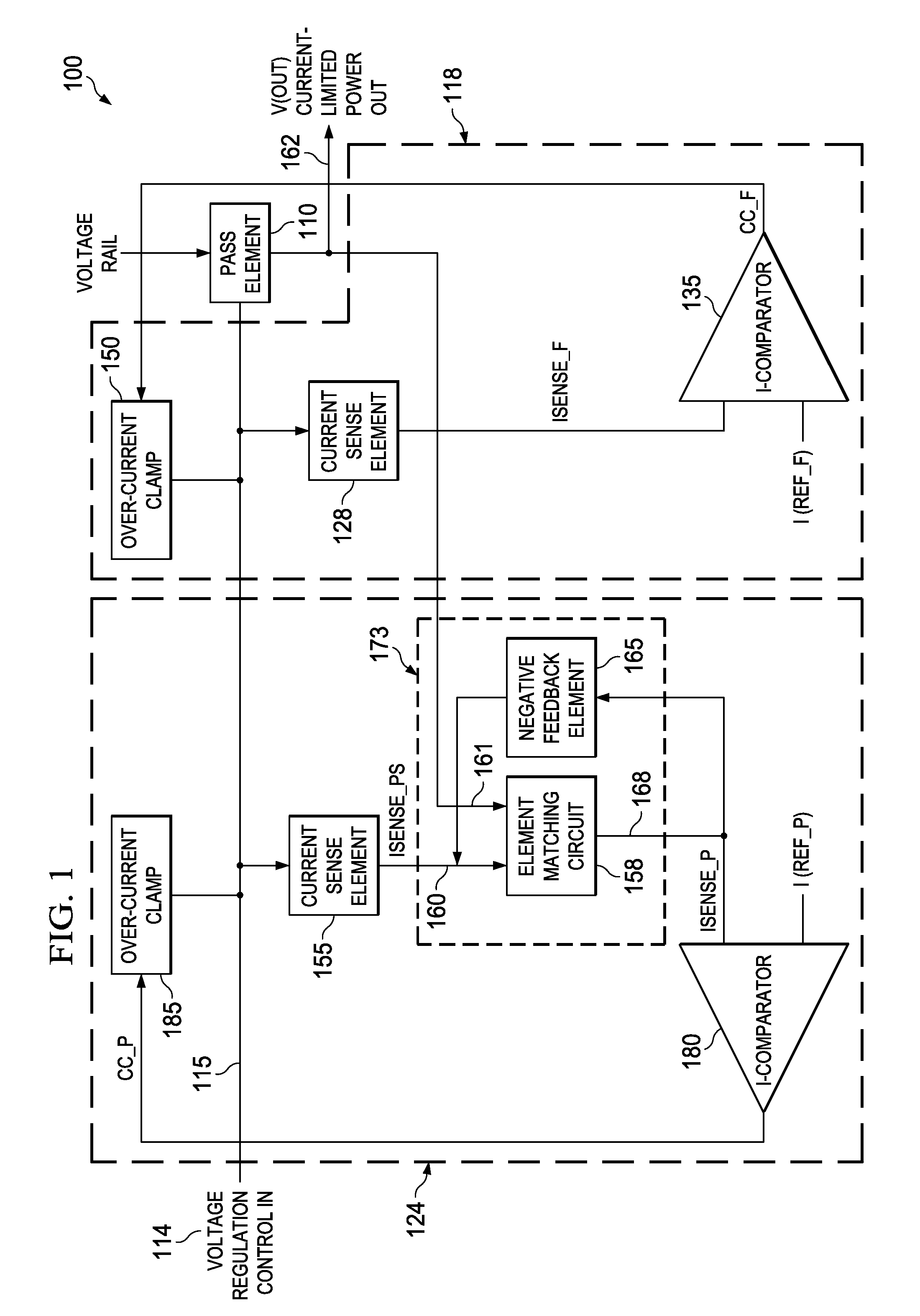
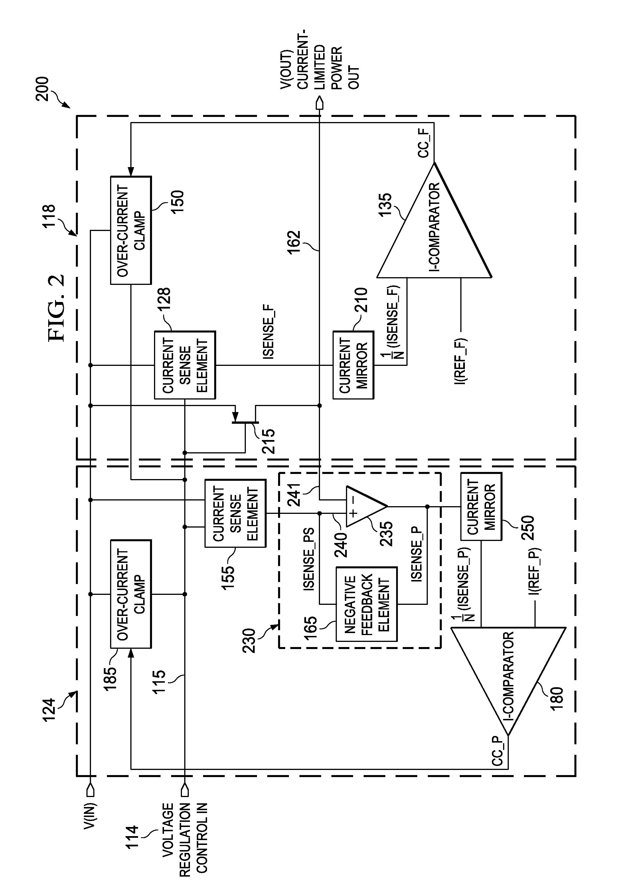
[0012]FIGS. 1 and 2 are block diagrams of current-limiting apparatus 100 and 200 according to various example embodiments of the invention. The current-limiting apparatus 100 and 200 include a pass element 110. The pass element 110 is embodied as a power MOSFET 215 in the current-limiting apparatus 200. The pass element 110 receives a voltage regulation control input signal 114 on a voltage regulation control input path 115. The pass element 110 allows a magnitude of current flow through a current channel of the pass element 110 that is proportional to the magnitude of the voltage regulation control input signal 114. The current-limiting apparatus 100 and 200 also both include a fast transient feedback circuit 118 and a precision feedback circuit 124 operating in parallel.

[0013]The fast transient feedback circuit 118 is communicatively coupled to the voltage regulation control input path 115. The fast transient feedback circuit 118 receives the voltage regulation control input signa...


PUM


Abstract

Apparatus disclosed herein implement a fast transient precision current limiter such as may be included in an electronic voltage regulator. The current limiter includes two current sense element/current clamp control loops. A fast response time control loop first engages and clamps a current spike. A precision control loop then engages to more accurately clamp the output current to a programmed set point. The precision clamping loop includes an inner loop to linearize the precision current sense element. The inner loop forces the drain-to-source voltage (VDS) of the precision sense element to track the VDS of the regulator pass element. A more precise clamping operation results. Overall speed is not sacrificed as the fast response time clamping loop operates in parallel to protect circuitry while the precision clamping loop engages.

Description

TECHNICAL FIELD[0001]Structures described herein relate to electronic circuits, including current-limiting circuits and electronic power supply systems.BACKGROUND INFORMATION[0002]Some electronic power supply regulators may include over-current protection circuitry. Over-current protection may prevent catastrophic failure of regulator components, particularly power transistor output stages, in the event of a short circuit or a heavy loading condition at the regulator output.[0003]Some power supply regulators may utilize a sense transistor to sense an overdrive condition and a current clamp to temporarily reduce the drive signal to the power output stage while the overdrive condition is present. However, sense transistor-based current clamps traditionally have poor direct current (DC) accuracy. Inaccuracies may be due to a combination of channel length modulation effects, sense element to pass element matching, and process, supply, and / or temperature (PVT) variations.BRIEF DESCRIPTIO...

Claims


Application Information

Patent Timeline
IPC IPC(8): H02H9/02
CPCH02H9/02
Inventor TORRES, HECTORPARKHURST, CHARLES
Owner TEXAS INSTR INC
Why Eureka
Try Eureka