Method for Optimizing HVAC Systems in Buildings Using Nonlinear Programming to Maximize Comfort for Occupants

a technology of hvac systems and nonlinear programming, applied in the direction of lighting and heating apparatus, heating types, instruments, etc., can solve problems such as non-smooth behavior, and achieve the effects of optimizing the operation of hvac systems, maximizing occupant comfort, and minimizing energy consumption

Inactive Publication Date: 2014-12-04
MITSUBISHI ELECTRIC RES LAB INC
View PDF1 Cites 7 Cited by
  • Summary
  • Abstract
  • Description
  • Claims
  • Application Information

AI Technical Summary

Benefits of technology

[0005]The embodiments of the invention provide a method for determining an optimal operation of a HVAC system by minimizing energy consumption, while maximizing occupant comfort. The building dynamics are modeled using differential equations that contro

Problems solved by technology

The PMV determinations involve conditional st

Method used


Image

  • Method for Optimizing HVAC Systems in Buildings Using Nonlinear Programming to Maximize Comfort for Occupants
  • Method for Optimizing HVAC Systems in Buildings Using Nonlinear Programming to Maximize Comfort for Occupants
  • Method for Optimizing HVAC Systems in Buildings Using Nonlinear Programming to Maximize Comfort for Occupants

Examples


Embodiment Construction

[0015]Building Representation

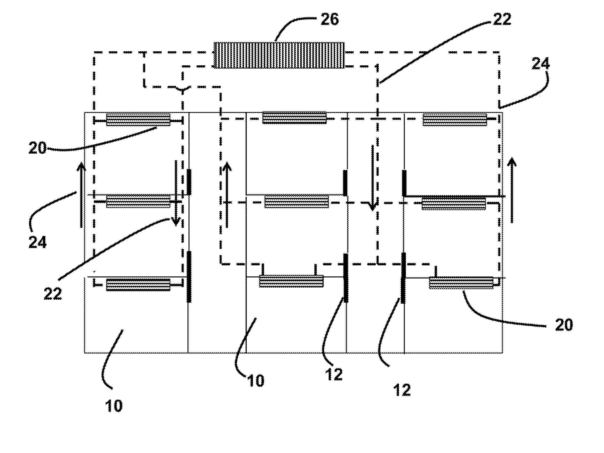
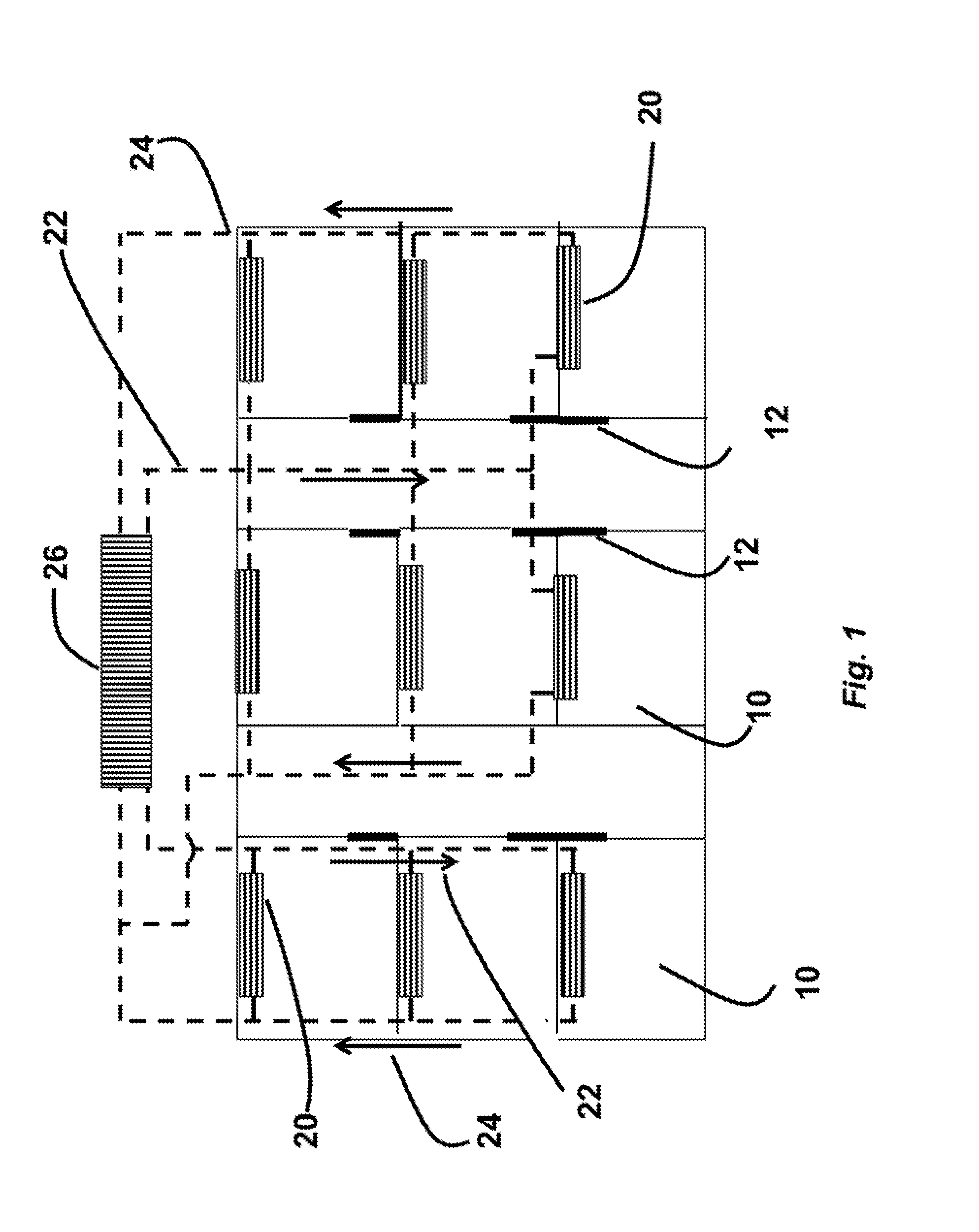
[0016]FIG. 1 shows a floor plan for a building that can be used by embodiments of our invention. The building includes rooms 10 and doors 12. Each room is equipped with an indoor air conditioning unit 20. The indoor units are connected to an outdoor unit 26. A refrigerant is used for cooling or heating room air flows 22 to the indoor units from the outdoor unit. The refrigerant flows (dashed lines) 24 from the indoor unit to the outdoor unit where the heat is dissipated and the refrigerant is recycled back to the indoor unit 22.

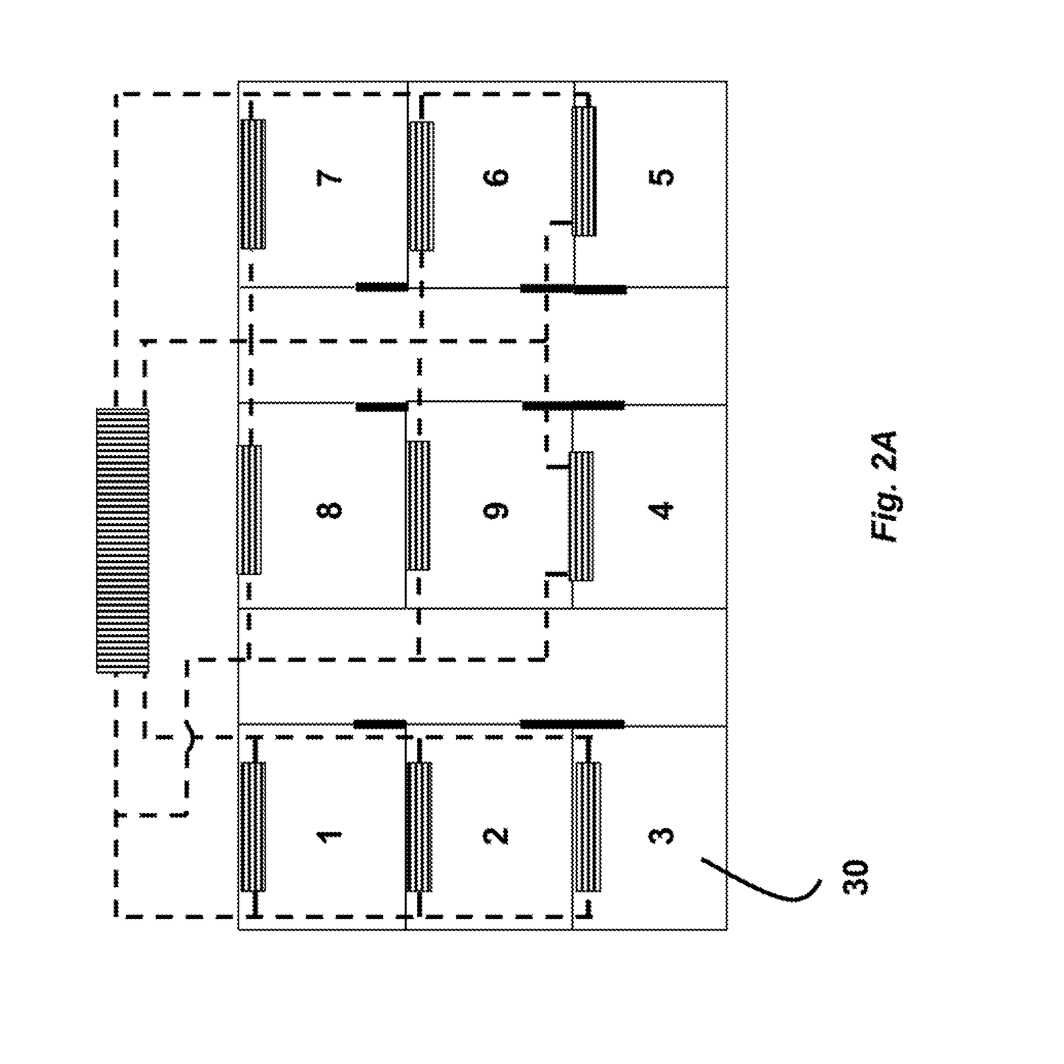
[0017]FIG. 2A shows a numbering of nine rooms 30 in the building, i.e., 1 to 9. The graph network representation in FIG. 2B based on this numbering. Nodes 40 represent the rooms in the building, and edges 42 represent the rooms that share a wall.

[0018]FIG. 3A provides a resistive capacitive network representation of the building model for thermal and humidity dynamics. The variables used in this figure and other similar figures ar...


PUM


Abstract

A heating, ventilation and air-conditioning (HVAC) system for a building is optimized while maximizing a comfort of occupants and minimizing energy consumption. The building is modeled as a network of nodes and edges, wherein the nodes represent rooms, and the edges represent walls. Dynamics of temperatures and humidity in the rooms and the temperature of the walls and the building are modeled using differential equations and the network. The comfort of the occupants is modeled by a predicted mean vote (PMV). The minimizing is formulated as an optimal control problem, which is discretized using an integration technique to obtain a finite dimensional optimization problem. Then, the finite dimensional optimization problem is solved using sparse linear algebra until convergence.

Description

FIELD OF THE INVENTION[0001]The present invention relates generally to controlling heating, ventilation and air conditioning (HVAC) systems in buildings, and more particularly to maximizing comfort for building occupants.BACKGROUND OF THE INVENTION[0002]The comfort of building occupants must be maximized while minimizing energy costs. Most conventional strategies for operating HVAC systems:(i) Do not consider the entire system. For instance, the control over multiple rooms in the building is usually decoupled to yield smaller loops over which the control actions are independently solved. This approach fails to consider the full coupling between the subsystems and can lead to poor performance.(ii) Do not consider thermal and humidity dynamics of the building that predict the evolution of temperature humidity over time.(iii) Do not consider occupant comfort metrics, such as a predicted mean vote (PMV), or thermal comfort zones during the determination of the operational strategies, an...

Claims


Application Information

Patent Timeline
IPC IPC(8): G06F17/50F24F11/00
CPCF24F11/0009G06F17/5009F24F11/30F24F2110/10F24F11/47G06F30/13G06F2119/06G06F30/367F24F11/46G06F30/20
Inventor RAGHUNATHAN, ARVIND U.NIKOVSKI, DANIEL N.
Owner MITSUBISHI ELECTRIC RES LAB INC
Why Eureka
Try Eureka