System and method for determining valve operation

a valve operation and valve technology, applied in mechanical equipment, machines/engines, electric control, etc., can solve the problems of engine emissions degrading, engine reactivation cannot be properly completed, engine cylinders are not properly reactivated, etc., to reduce engine pumping losses, increase the efficiency of active cylinders, and save fuel

Inactive Publication Date: 2014-12-11
FORD GLOBAL TECH LLC
View PDF5 Cites 53 Cited by
  • Summary
  • Abstract
  • Description
  • Claims
  • Application Information

AI Technical Summary

Benefits of technology

[0001]Cylinders of an engine may be selectively deactivated to conserve fuel. For example, four cylinders of an eight cylinder engine may be deactivated while at the same time the four remaining cylinders continue to operate. Deactivating four of eight cylinders increases the efficiency of the active cylinders while reducing engine pumping losses. One way to deactivate an engine cylinder is to cease fuel flow to the cylinder and hold a cylinder's intake and exhaust valves in a closed position during an engine cycle. The engine may continue to rotate without pumping air through the deactivated cylinder. The cylinder may be reactivated by injecting fuel to the cylinder and restarting opening and closing of the cylinder's intake and exhaust valves. However, it may be possible that a cylinder does not properly reactivate after it has been deactivated. For example, the cylinder's intake and / or exhaust valves may remain closed as the engine rotates. Consequently, the engine may not have its full rated power and engine emissions may degrade if the inactive cylinder is not detected.

Problems solved by technology

However, it may be possible that a cylinder does not properly reactivate after it has been deactivated.
Consequently, the engine may not have its full rated power and engine emissions may degrade if the inactive cylinder is not detected.

Method used


Image

  • System and method for determining valve operation
  • System and method for determining valve operation
  • System and method for determining valve operation

Examples


Embodiment Construction

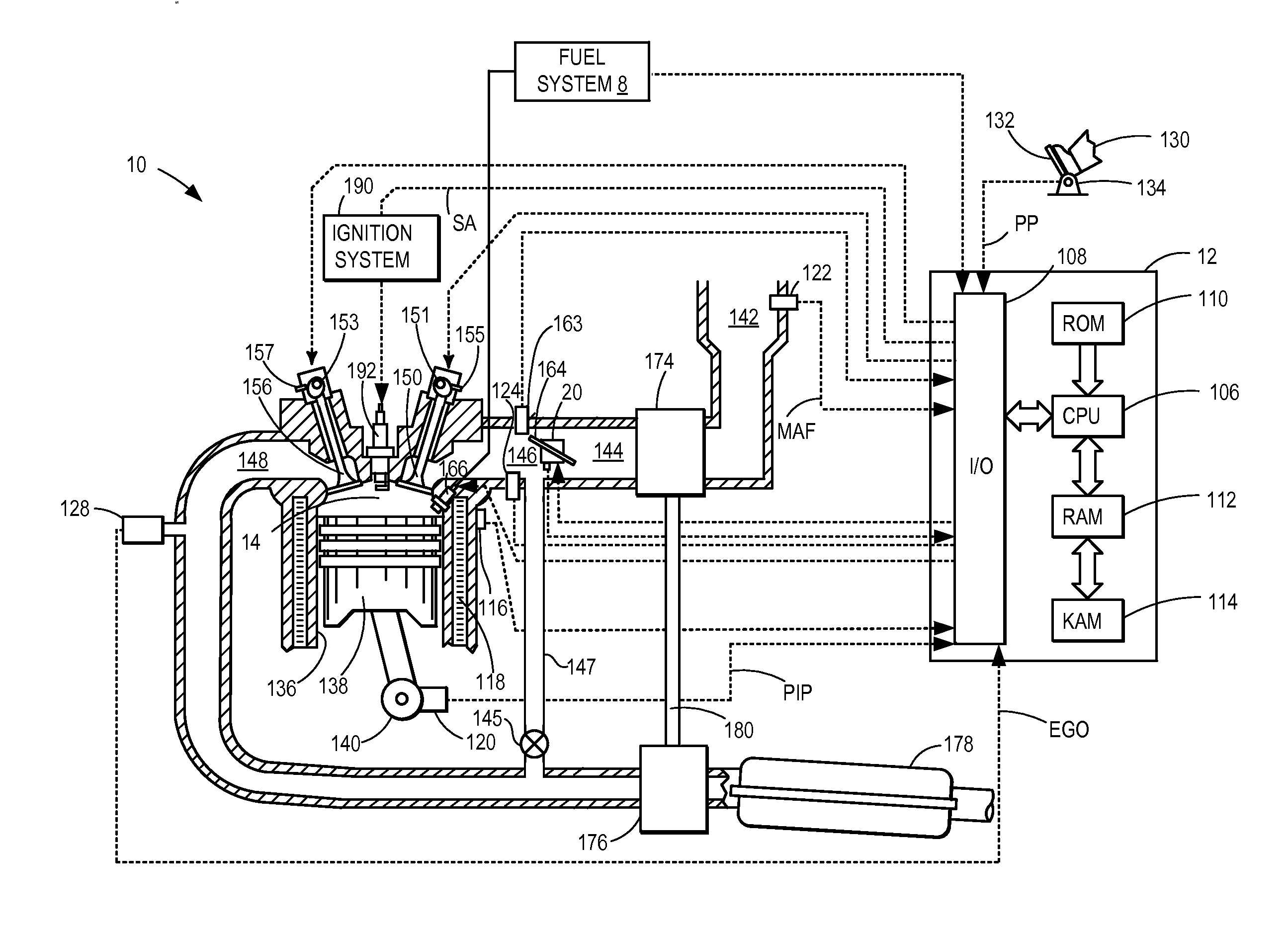
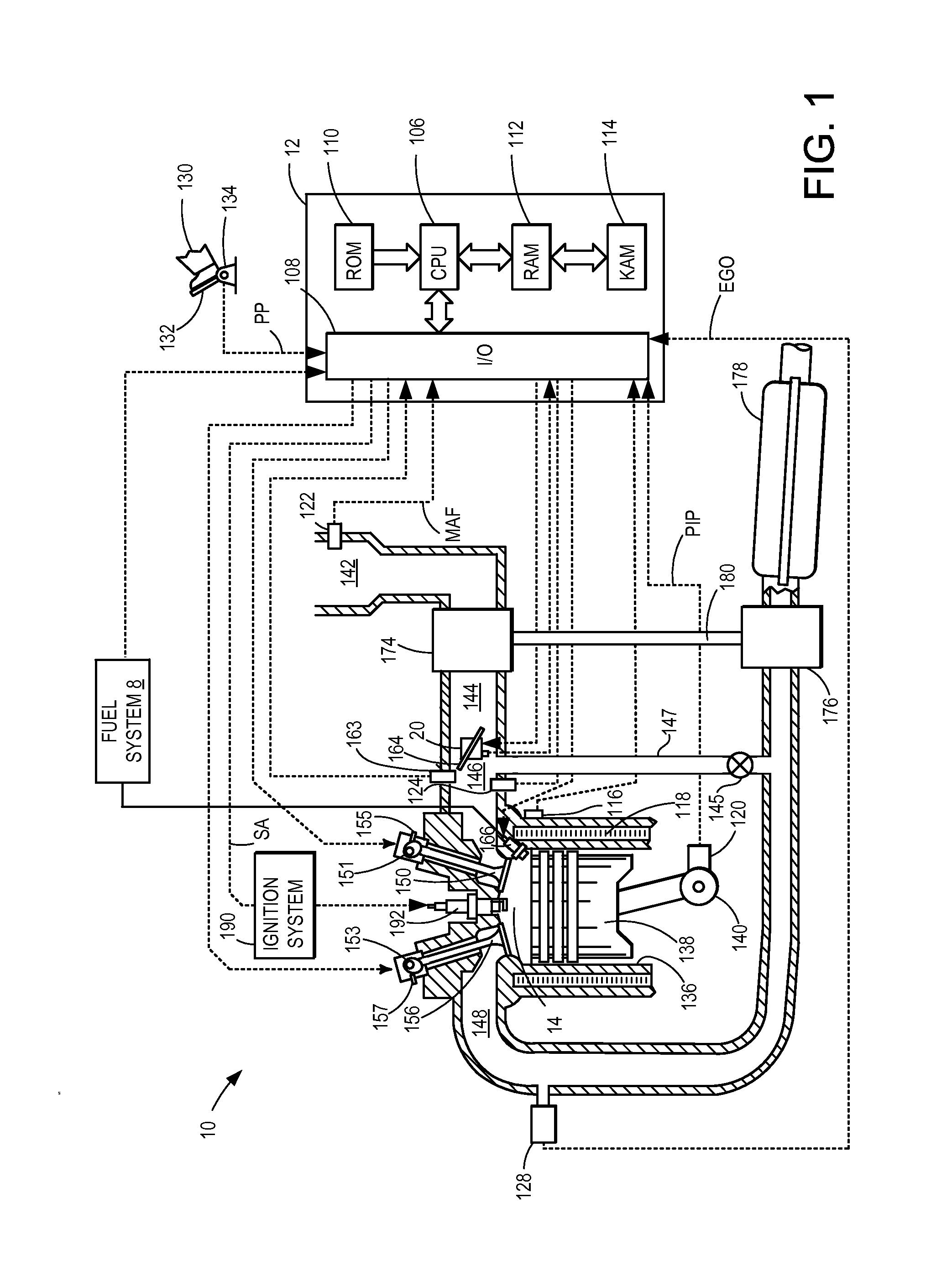
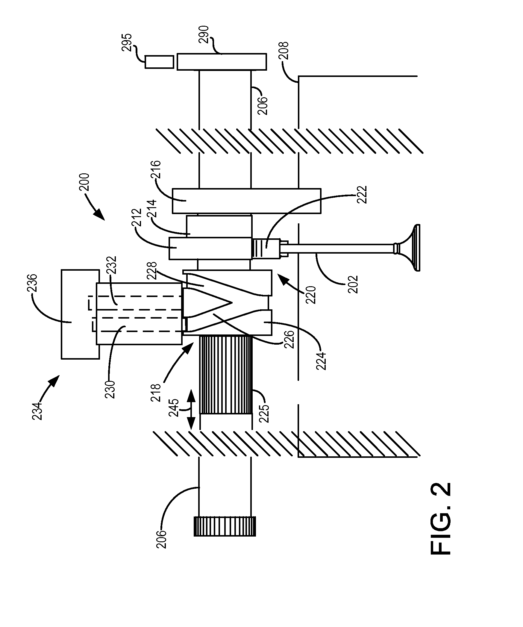
[0009]The following description relates to systems and methods for determining degradation of a valve operating device. In one example, the valve operating device may be included in an engine system as is shown in FIG. 1. FIG. 2 shows an example valve operating device that selectively activates and deactivates valves. An engine operating sequence is shown in FIG. 3 where engine intake manifold oxygen concentration is a basis for determining exhaust valve degradation. Finally, FIG. 4 shows an example method for operating an engine and determining exhaust valve degradation in response to intake manifold oxygen concentration.

[0010]Referring now to FIG. 1, it depicts an example of a combustion chamber or cylinder of internal combustion engine 10. Engine 10 may receive control parameters from a control system including controller 12 and input from a vehicle operator 130 via an input device 132. In this example, input device 132 includes an accelerator pedal and a pedal position sensor 13...


PUM


Abstract

Systems and methods for determining operation of a cylinder deactivating/reactivating device are disclosed. In one example, degradation of the cylinder deactivating/reactivating device is based on intake manifold oxygen concentration.

Description

BACKGROUND AND SUMMARY[0001]Cylinders of an engine may be selectively deactivated to conserve fuel. For example, four cylinders of an eight cylinder engine may be deactivated while at the same time the four remaining cylinders continue to operate. Deactivating four of eight cylinders increases the efficiency of the active cylinders while reducing engine pumping losses. One way to deactivate an engine cylinder is to cease fuel flow to the cylinder and hold a cylinder's intake and exhaust valves in a closed position during an engine cycle. The engine may continue to rotate without pumping air through the deactivated cylinder. The cylinder may be reactivated by injecting fuel to the cylinder and restarting opening and closing of the cylinder's intake and exhaust valves. However, it may be possible that a cylinder does not properly reactivate after it has been deactivated. For example, the cylinder's intake and / or exhaust valves may remain closed as the engine rotates. Consequently, the...

Claims


Application Information

Patent Timeline
Patent Type & Authority Applications(United States)
IPC IPC(8): F02D41/14F02D41/00
CPCF02D41/008F02D41/144F02D37/02F02D41/0052F02D41/0087F02D41/221F02D2041/001F02D2250/22F02P5/00F02P9/00Y02T10/40F02D17/02F02M26/00
Inventor DOERING, JEFFREY ALLENGLUGLA, CHRIS PAULUHRICH, MICHAEL JAMES
Owner FORD GLOBAL TECH LLC
Why Eureka
Try Eureka