Remote control system for pointing robot

a remote control system and robot technology, applied in the field of remote control systems, can solve the problems of long response time and low accuracy and the user's inability to intuitively control the direction of the remote control system in the conventional remote control system,

Active Publication Date: 2014-12-11
PIXART IMAGING INC
View PDF2 Cites 8 Cited by
  • Summary
  • Abstract
  • Description
  • Claims
  • Application Information

AI Technical Summary

Benefits of technology

[0018]The remote control system for the pointing robot according to the embodiment of the present disclosure may determine a turning angle, a moving direction and / or a travel distance of the controlled device according to light source images of the controlled device through vector operations. Accordingly, a user can control motions of the controlled device more intuitively.

Problems solved by technology

However, as the user's visual line is not consistent with the current moving direction of a controlled device, the user has to consider the steering based on the visual line of the controlled device during operation.
Therefore, the direction control in the conventional remote control system is not intuitive for the user.
Meanwhile, as the identifying process can be easily interfered by ambient light thus the remote control system has problems of long response time and low accuracy.

Method used


Image

  • Remote control system for pointing robot
  • Remote control system for pointing robot
  • Remote control system for pointing robot

Examples


first embodiment

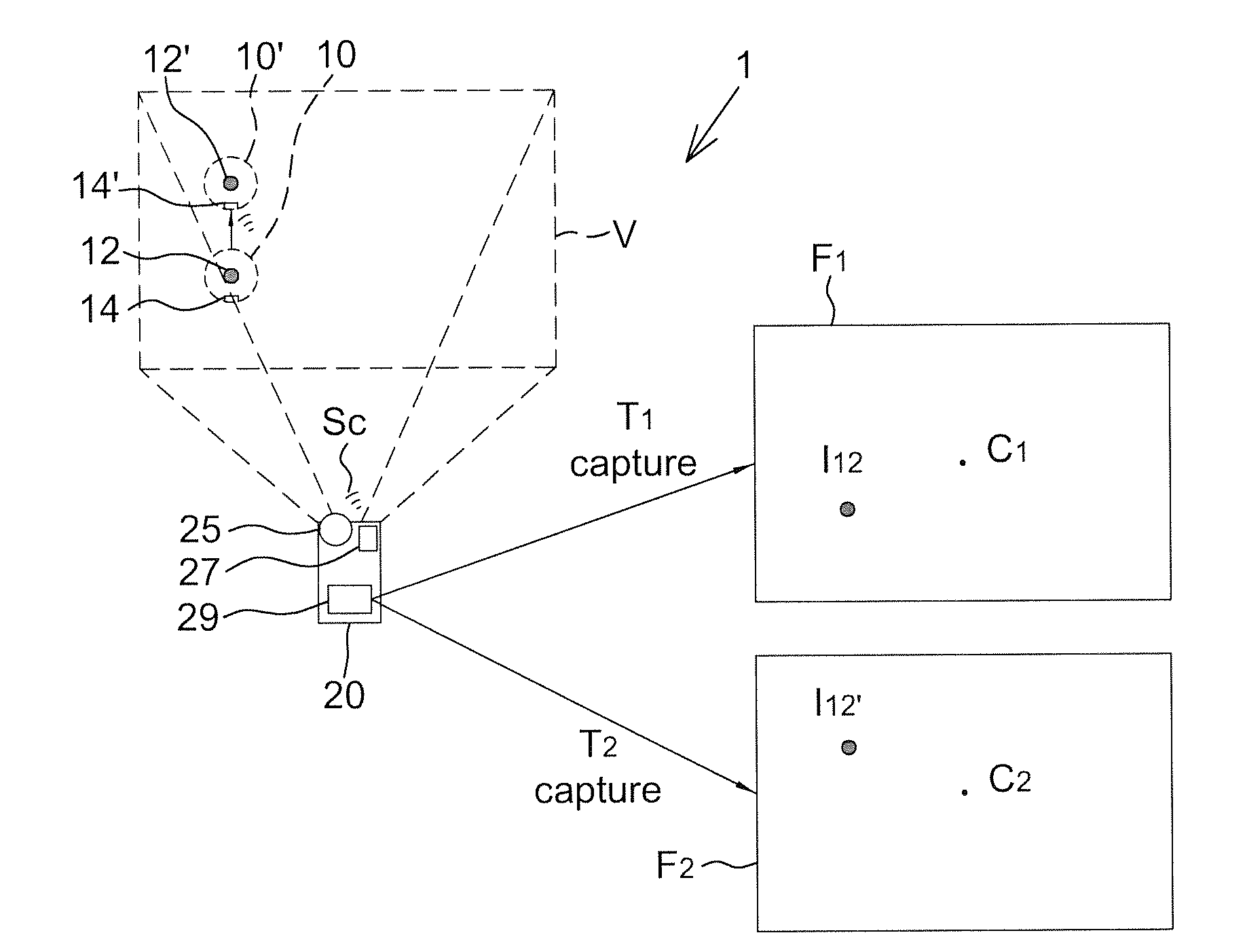
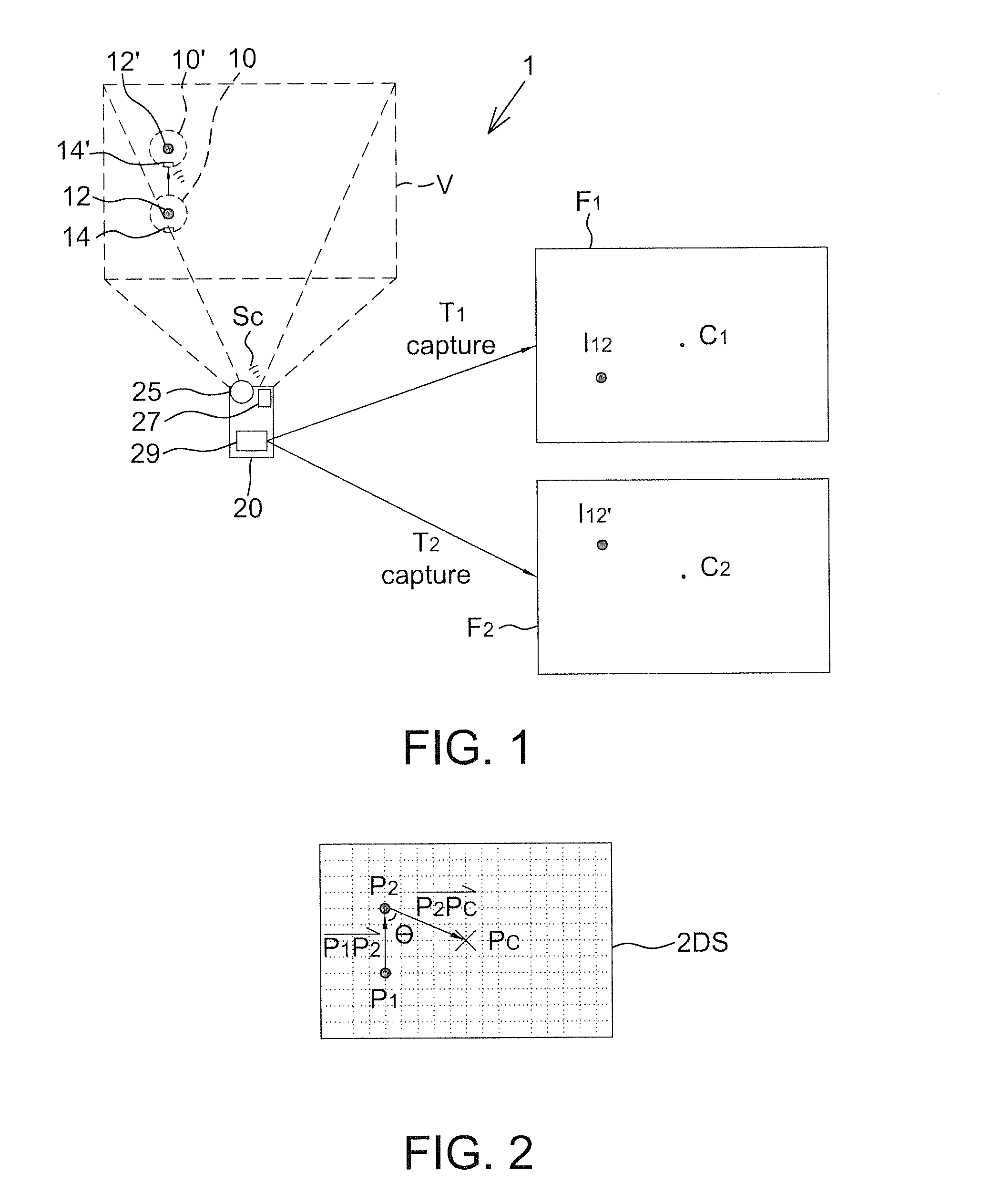
[0028]FIG. 1 shows a schematic diagram of a remote control system 1 according to the present disclosure, for example the remote control system for a pointing robot. The remote control system 1 includes a controlled device 10 and a remote device 20. A user may control the controlled device 10 though the remote device 20, for example controlling a moving direction, a moving velocity, a travel distance, a turning angle and / or an operating strength of the controlled device 10.

[0029]The controlled device 10 has a light source 12 and a receiver 14. The light source 12 may emit light with an adjustable flicker frequency or light on constantly without the flicker to be served as a reference point for detecting positions of the controlled device 10. The receiver 14 is configured to perform one-way or two-way communication with the remote device 20. It should be mentioned that the position of the light source 12 of the controlled device 10 shown in FIG. 1 is not used to limit the present disc...

second embodiment

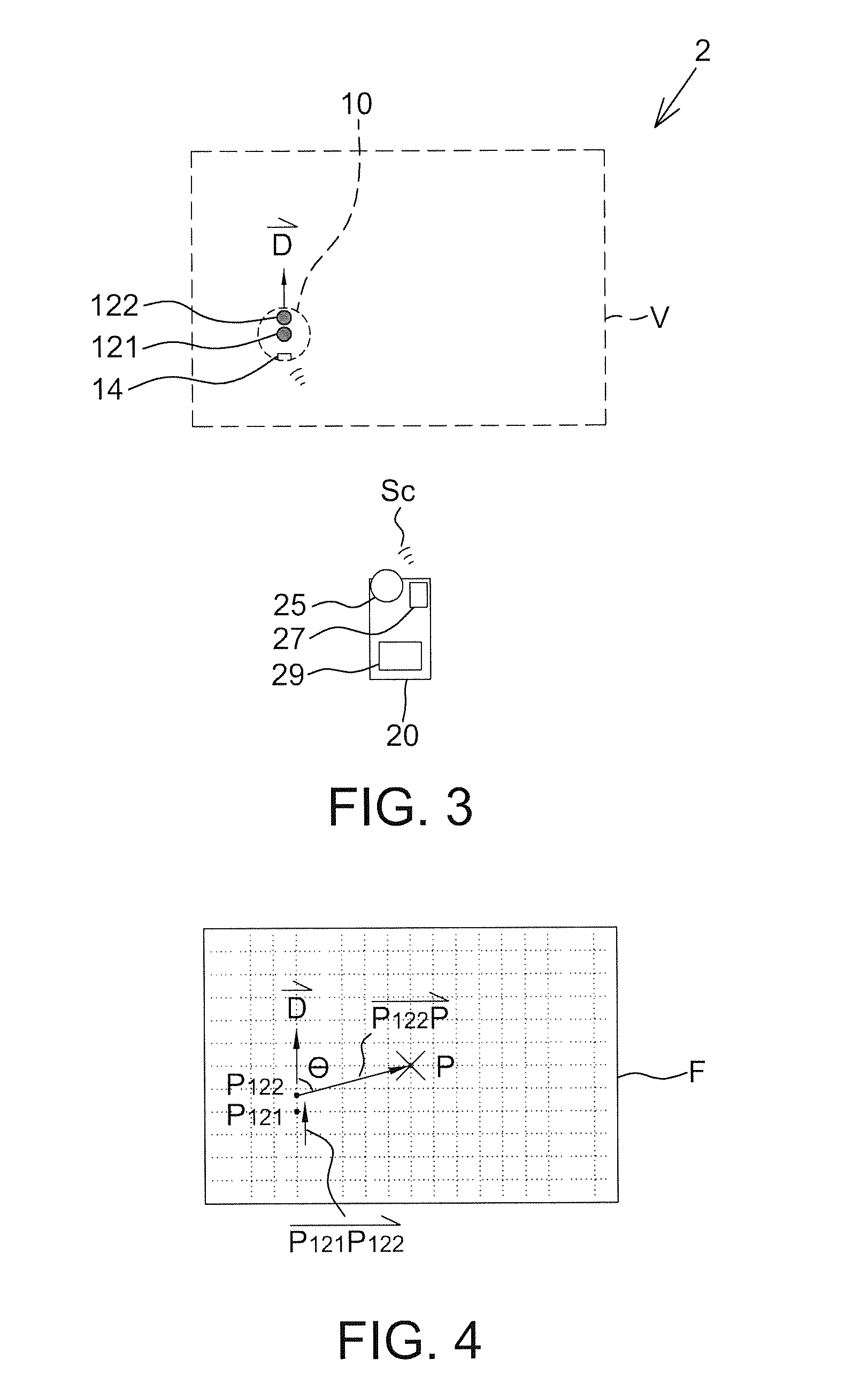
[0040]FIG. 3 shows a schematic diagram of a remote control system 2 according to the present disclosure, and the system may be a remote control system for a pointing robot and include a controlled device 10 and a remote device 20 as well. Similarly, a user may control the controlled device 10 through the remote device 20, e.g. controlling an operating mode, a moving direction, a turning angle, a moving velocity, a travel distance and / or an operating strength.

[0041]The controlled device 10 has a first light source 121, a second light source 122 and a receiver 14, and moves in a predetermined moving direction {right arrow over (D)} (e.g. ahead of the controlled device 10). The first light source 121 and the second light source 122 have different characteristics (described later) so as to be distinguished by the remote device 20. The receiver 14 is configured to perform one-way or two-way communication with the remote device 20. It should be mentioned that the positions of the first li...

third embodiment

[0052]FIG. 5 shows a schematic diagram of a remote control system 3 according to the present disclosure, and the system may be a remote control system for a pointing robot and include a controlled device 10 and a remote device 20 as well. Similarly, a user can control the controlled device 10 through the remote device 20, e.g. controlling an operating mode, a moving direction, a turning angle, a moving velocity, a travel distance and / or an operating strength of the controlled device 10.

[0053]The controlled device 10 has a light source 12 and a receiver 14 and moves in a predetermined moving direction {right arrow over (D)}, wherein the light source 12 has a predetermined pattern configured to correspond to the predetermined moving direction {right arrow over (D)} (e.g. an arrow pattern pointing toward the predetermined moving direction {right arrow over (D)} as shown in FIG. 5). The light source 12 emits light with an adjustable flicker frequency or lights on continually to be serve...


PUM


Abstract

There is provided a remote control system including a controlled device and a remote device. The controlled device has a light source and moves according to a control signal from the remote device. The remote device is adapted to be operated by a user and includes an image sensor. The remote device determines a moving direction of the controlled device according to an imaging position of the light source in the image captured by the image sensor and a pointing position of the user, and outputs the control signal.

Description

RELATED APPLICATIONS[0001]The present application is based on and claims priority to Taiwanese Application Number 102120456, filed Jun. 7, 2013, the disclosure of which is hereby incorporated by reference herein in its entirety.BACKGROUND[0002]1. Field of the Disclosure[0003]This disclosure generally relates to a remote control system and, more particularly, to a remote control system for a pointing robot.[0004]2. Description of the Related Art[0005]The conventional remote control system includes, for example, a remote control car and a remote controller. The remote control car can move according to an electric wave signal sent by the remote controller. The remote control car generally includes a switch configured to activate a receiver so as to allow the remote control car to standby or move straight at a predetermined velocity. The remote controller includes a plurality of buttons thereon, for example, including a plurality of direction keys configured to control moving directions...

Claims


Application Information

Patent Timeline
Patent Type & Authority Applications(United States)
IPC IPC(8): G08C23/04
CPCG08C23/04G08C17/02H04N23/80B25J9/161B25J11/0085A63H30/04G05D1/0016G05D1/0033G05D1/0246G05D2201/0214
Inventor HUANG, SEN-HUANGKO, YI-HSIEN
Owner PIXART IMAGING INC
Why Eureka
Try Eureka