Supercharge Your Innovation With Domain-Expert AI Agents!

Exposure apparatus and method of manufacturing article

a technology of exposure apparatus and manufacturing method, which is applied in the direction of microlithography exposure apparatus, printers, instruments, etc., can solve the problems of generating errors in the result of focus measurement, and it is difficult to accurately transfer the pattern of the mask onto the substrate, so as to achieve accurate transfer of the mask pattern onto the substrate

Active Publication Date: 2014-12-11
CANON KK
View PDF11 Cites 0 Cited by
  • Summary
  • Abstract
  • Description
  • Claims
  • Application Information

AI Technical Summary

Benefits of technology

The present invention is an exposure apparatus that can accurately transfer the pattern of a mask onto a substrate. This leads to improved accuracy and efficiency in the manufacturing process.

Problems solved by technology

However, since a reaction force is generated along with acceleration or deceleration of the substrate stage in the exposure apparatus, the frame structure in the exposure apparatus is deformed and thereby an error in the result of focus measurement may be generated.
It may become difficult to accurately transfer the pattern of a mask onto a substrate.
However, a shot region (unexposed shot region) which has not been exposed because the exposure condition was not satisfied till the start of exposure may be generated among a plurality of shot regions.

Method used


Image

  • Exposure apparatus and method of manufacturing article
  • Exposure apparatus and method of manufacturing article
  • Exposure apparatus and method of manufacturing article

Examples


first embodiment

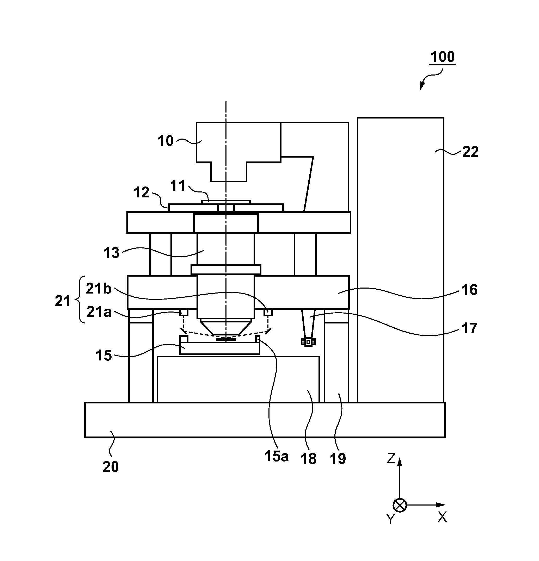
[0020]An exposure apparatus 100 according to the first embodiment of the present invention will be described with reference to FIG. 1. FIG. 1 is a view showing the exposure apparatus 100 according to the first embodiment of the present invention. The exposure apparatus 100 according to the first embodiment is a step & scan type scanning exposure apparatus which scans and exposes a substrate with slit-shaped light. The exposure apparatus 100 includes an illumination optical system 10, mask stage 12, projection optical system 13, substrate stage 15, position measurement unit 17, focus measurement unit 21, and control unit 22. The control unit 22 includes a CPU and memory, and controls the overall exposure apparatus 100 (the respective units of the exposure apparatus 100). More specifically, the control unit 22 controls processing of transferring, onto a substrate 14, a pattern formed on a mask 11 (processing of scanning and exposing the substrate 14). The projection optical system 13 ...

second embodiment

[0037]The second embodiment will explain a method of exposing a shot region which has not been exposed because the exposure condition was not satisfied in a step & repeat exposure apparatus. The step & repeat exposure apparatus does not drive a substrate stage 15 when exposing a shot region 14a, and exposes the shot region 14a in a state in which the substrate stage 15 is stopped. In the exposure apparatus according to the second embodiment, an irradiation region 25 irradiated with light on a substrate becomes equal in size to the shot region 14a. The arrangement of the exposure apparatus according to the second embodiment is the same as that of the exposure apparatus 100 according to the first embodiment, and a description thereof will not be repeated.

[0038]Drive information of the substrate stage 15 in exposure processing in the exposure apparatus according to the second embodiment will be explained with reference to FIGS. 8 and 9. FIG. 8 is a chart showing drive information of th...


PUM


Abstract

The present invention provides an exposure apparatus which exposes each of a plurality of shot regions on a substrate, comprising a substrate stage configured to be movable while holding the substrate, and a control unit, wherein the plurality of shot regions include a first shot region, and a second shot region which is exposed next to the first shot region, and the control unit drives the substrate stage in accordance with drive information of the substrate stage in a period until exposure of the second shot region starts after an end of exposing the first shot region, and when an exposure condition for exposing the second shot region is not satisfied in the period, the control unit drives again the substrate stage in accordance with the drive information and then exposes the second shot region.

Description

BACKGROUND OF THE INVENTION[0001]1. Field of the Invention[0002]The present invention relates to an exposure apparatus and a method of manufacturing an article.[0003]2. Description of the Related Art[0004]One of apparatuses used in a manufacturing step (lithography step) for a semiconductor device or the like is an exposure apparatus which transfers the pattern of a mask onto a substrate. The exposure apparatus needs to accurately transfer the pattern of a mask onto a substrate. For this purpose, it is important to make the imaging plane (focus plane) of the projection optical system coincide with the substrate surface in the exposure apparatus. The exposure apparatus therefore performs focus measurement to measure the height of the substrate surface.[0005]However, since a reaction force is generated along with acceleration or deceleration of the substrate stage in the exposure apparatus, the frame structure in the exposure apparatus is deformed and thereby an error in the result of...

Claims


Application Information

Patent Timeline
IPC IPC(8): G03F7/20G03F9/00
CPCG03F7/70725G03F2009/005G03F9/7049
Inventor ITO, SATORU
Owner CANON KK
Features
  • R&D
  • Intellectual Property
  • Life Sciences
  • Materials
  • Tech Scout
  • Unparalleled Data Quality
  • Higher Quality Content
  • 60% Fewer Hallucinations
Learn More