Exhaust aftertreatment system and method for operating the system

a technology of exhaust aftertreatment and exhaust, which is applied in the direction of exhaust treatment electric control, machines/engines, separation processes, etc., can solve the problems of affecting the operation affecting the efficiency of the exhaust aftertreatment system, and a relatively short refill interval of the ammonia source, etc., to achieve rapid and economical control, rapid warm-up of the catalys

Active Publication Date: 2014-12-11
VOLVO LASTVAGNAR AB
View PDF5 Cites 80 Cited by
  • Summary
  • Abstract
  • Description
  • Claims
  • Application Information

AI Technical Summary

Benefits of technology

[0034]According to an aspect of the invention, said first SCR catalyst is arranged less than 0.6 metres downstream from an exhaust manifold outlet or turbo exhaust outlet of said engine, preferably less than 0.4 metres downstream from an exhaust manifold outlet or turbo exhaust outlet, and more preferably less than 0.25 metres downstream from an exhaust manifold outlet or turbo exhaust outlet. By arranging the first SCR catalyst more close to the exhaust manifold outlet, or turbo exhaust outlet if a turbocharger is provided, the exhaust gases passing through the first SCR catalyst will be warmer, thereby facilitating a more rapid warm-up of said catalyst.
[0035]According to an aspect of the invention, an electronic controller is configured to control injection of fluid ammonia-containing reductant by said second injector. The electronic controller allows fast and economical control of the exhaust aftertreatment system in general, especially with respect to the particular dosing strategy used by the inventive system.

Problems solved by technology

This system however exhibits a limited efficiency for removal of the above mentioned pollutants during low-temperature exhaust conditions, such as after cold start of the engine, or during low-temperature operation, e.g. low-speed urban driving conditions.
Another problem with efficient exhaust treatment systems in general is relatively short refill-intervals of the ammonia-source that is required for operation of the SCR catalyst.
Still another problem with efficient exhaust treatment systems is the physical size of the system and the limited space available in modern vehicles, rendering packaging of the exhaust aftertreatment system difficult.
When injecting a fluid ammonia-containing reductant, such as urea, the decomposition reaction of said reductant to active reagent gaseous ammonia within the exhaust passage requires a certain temperature level of the exhaust gases at the injection position for substantially complete decomposition, e.g. normally around 200° C. Injection of the ammonia-containing reductant can thus not be initiated much below said temperature level, thereby strongly limiting the NOx emission abatement efficiency.
This type of dosing strategy, which is possible by means of the inventive arrangement, does not only enables a very high NOx conversion efficiency without any penalty to fuel economy but also results in significantly extended service intervals of the exhaust aftertreatment system, i.e. longer time periods between refill or exchange of the ammonia sources.
Due to the limited volume, the first SCR catalyst may not have the capacity to alone provide sufficient catalytic removal of NOx emission in the upper operating load region of the engine, i.e. upon high power demand, but the capacity is sufficient in the engine operating conditions normally associated with cold-start and low-temperature exhaust gas urban driving, i.e. a relatively low operating engine load.
There is thus a problem of extremely high heat at the position of the first injector.
This type of dosing strategy, which is possible by means of the inventive arrangement, does not only enable a very high NOx conversion efficiency without any penalty to fuel economy but also result in significantly extended service intervals of the exhaust aftertreatment system, i.e. longer time periods between refill or exchange of the ammonia sources.

Method used


Image

  • Exhaust aftertreatment system and method for operating the system
  • Exhaust aftertreatment system and method for operating the system
  • Exhaust aftertreatment system and method for operating the system

Examples


Embodiment Construction

[0044]Various aspects of the invention will hereinafter be described in conjunction with the appended drawings provided to illustrate and not to limit the invention.

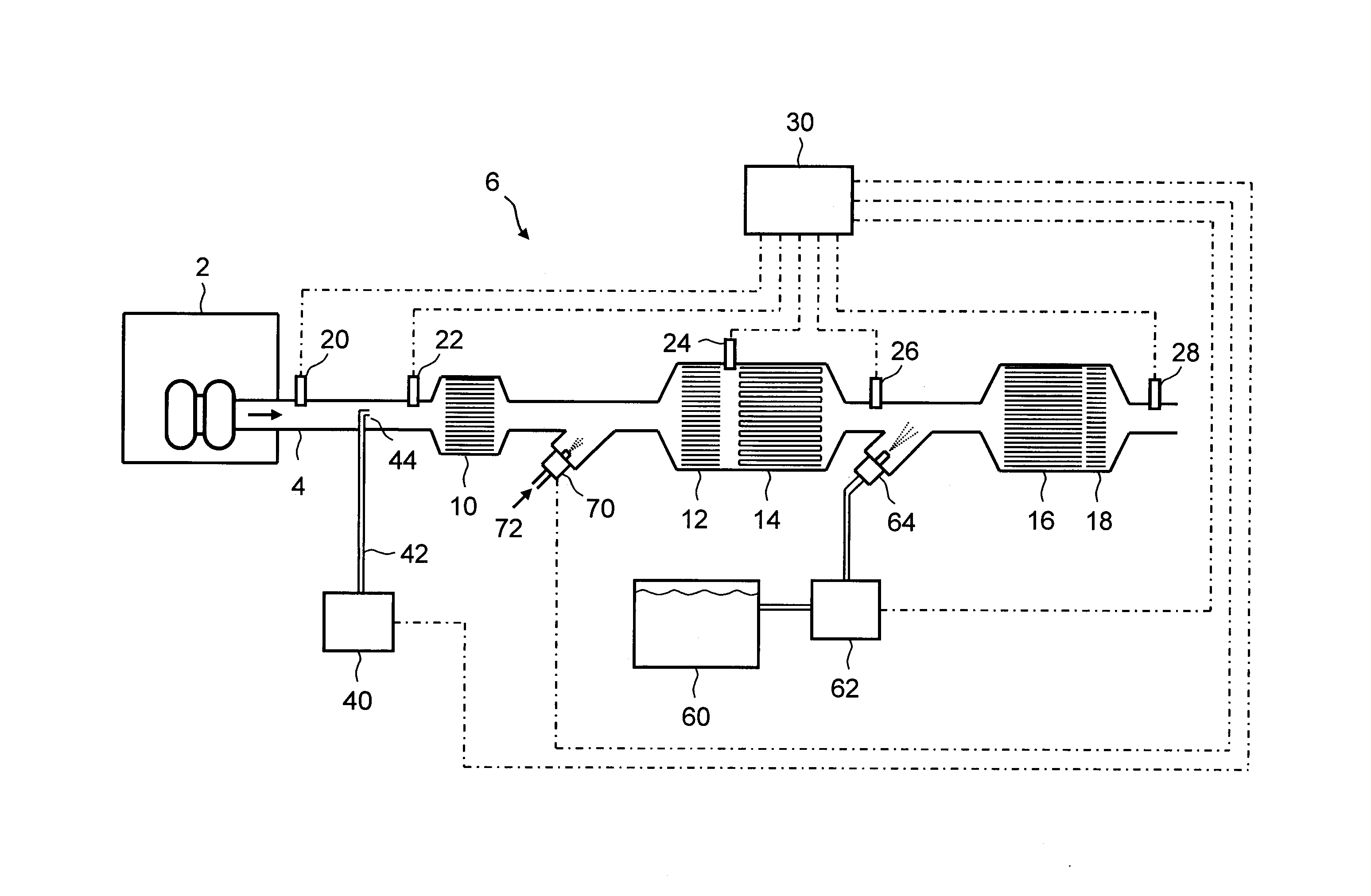
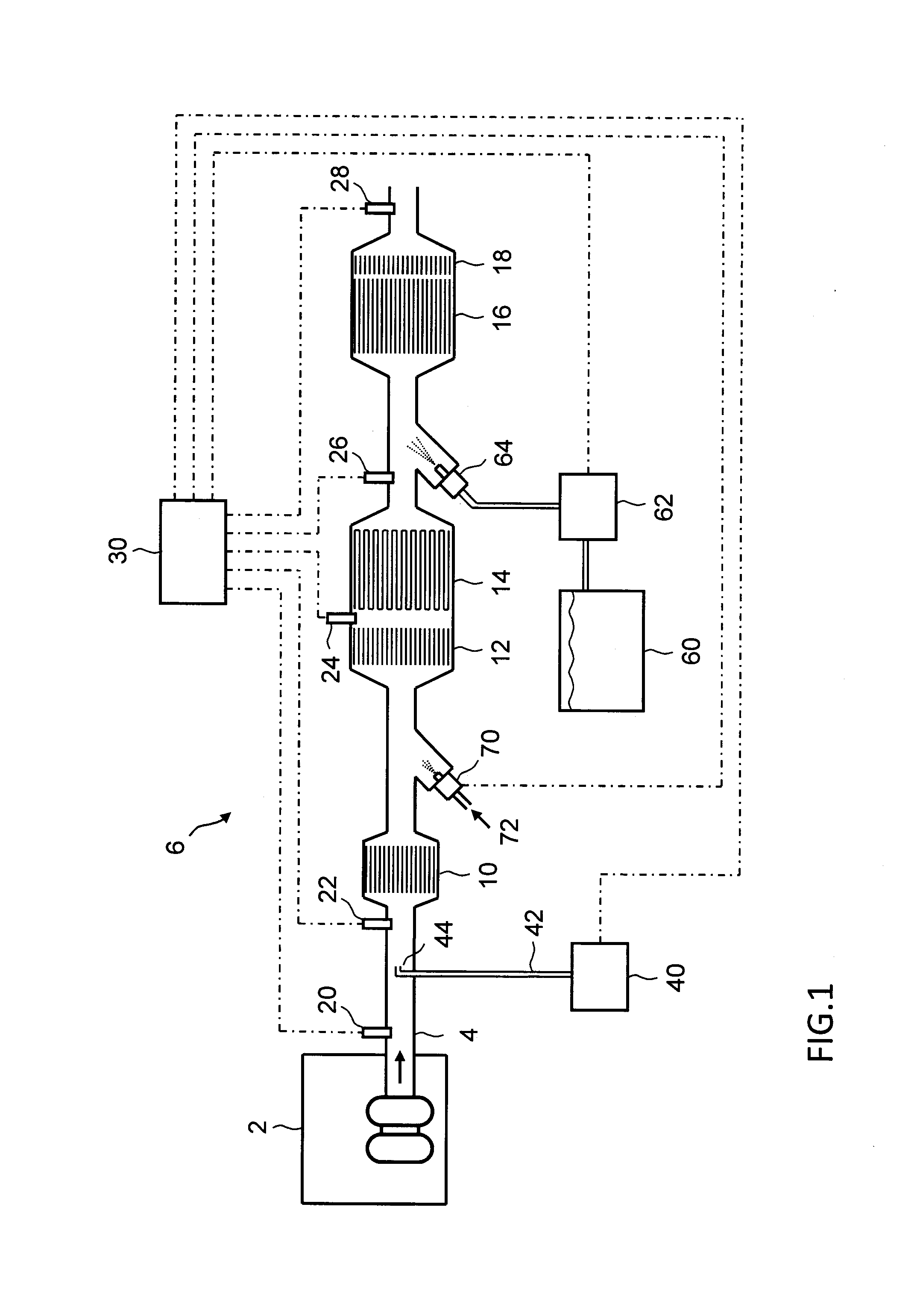
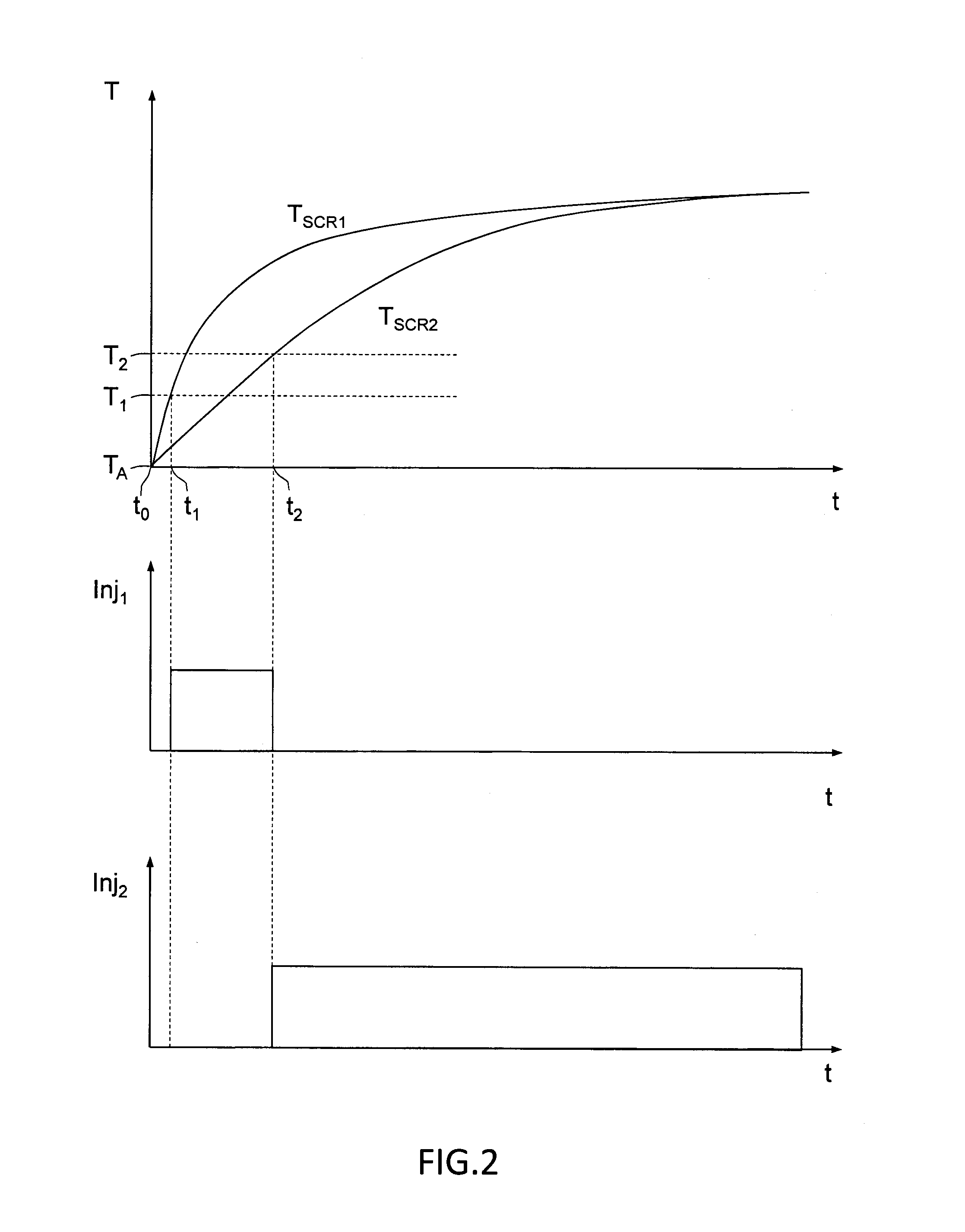
[0045]The use of selective catalytic reduction (SCR) for reducing NOx emissions is widespread within the automotive industry, with the most common technology using, urea (NH2CONH2) as a precursor to ammonia (NH3) for the catalytic removal of NOx emissions. The invention is not limited to urea as ammonia-containing reductant, and other reductant types currently used in SCR applications may alternatively be used, such as aqueous ammonia. The NOx abatement efficiency of an SCR catalyst has a two-fold temperature dependence, limiting the efficiency during low-temperature exhaust conditions. The reaction rates of the catalytic reactions for NOx removal are dependent on temperature, with an active temperature window generally starting at a catalyst temperature of e.g. 150° C., depending also on the NO:NO2 ratio of the feedgas ...


PUM

PropertyMeasurementUnit
temperatureaaaaaaaaaa

Abstract

An exhaust system includes a first SCR catalyst and a second SCR catalyst positioned downstream of the first SCR catalyst. A first injector is provided upstream of the first SCR catalyst, and a second injector is provided upstream of the second SCR catalyst. The exhaust system further includes a gaseous ammonia supply device fluidly connected to the first injector for supplying gaseous ammonia to the exhaust gas by the first injector, and an ammonia-containing reductant reservoir fluidly connected to the second injector for supplying a fluid ammonia-containing reductant, such as urea, to the exhaust gas by the second injector. The first SCR catalyst has a smaller volume than the second SCR catalyst for a fast warm-up of the first SCR catalyst.

Description

BACKGROUND AND SUMMARY[0001]The present invention relates to an exhaust system for receiving an exhaust gas, wherein the exhaust system comprising a first SCR catalyst, a second SCR catalyst positioned downstream of said first SCR catalyst, a first injector provided upstream of said first SCR catalyst, and a second injector provided upstream of said second SCR catalyst.[0002]Engines, in particular diesel-powered combustion engines but also other engines known in the art, produce exhaust gases which contain several air pollutants, including carbon monoxide (CO), hydrocarbons (HC), nitrogen oxides NO and NO2 (NOx) as well as particulate matter (PM) containing carbonaceous matter, or soot.[0003]With increased attention to environmental problems and health hazard prevention, exhaust emission regulations are becoming more and more stringent.[0004]To reduce the amount of NOx in the exhaust gases, some engines are equipped with Selective Catalytic. Reduction (SCR) systems that convert a mi...

Claims


Application Information

Patent Timeline
Patent Type & Authority Applications(United States)
IPC IPC(8): B01D53/94
CPCB01D53/9431F01N3/035F01N3/106F01N3/208F01N3/28F01N9/00F01N13/0093F01N2340/00F01N2610/01F01N2610/02F01N2610/06F01N2900/1602Y02T10/24Y02T10/12Y02T10/40
Inventor UDD, SORENKORSGREN, JOHN
Owner VOLVO LASTVAGNAR AB
Why Eureka
Try Eureka