
Laminate Structure

Inactive Publication Date: 2014-12-11
MITSUBISHI RAYON CO LTD
View PDF5 Cites 4 Cited by
  • Summary
  • Abstract
  • Description
  • Claims
  • Application Information

AI Technical Summary

Benefits of technology

The laminate structure described in this patent prevents the adhesive film from peeling off the surface of an article unintentionally. It is easy to peel off when intended and leaves minimal residue on the microrelief structure.

Problems solved by technology

For various image display units, lens, show-windows, and the like, a degradation of visibility is a problem because the light of the sun, a lighting, and the like is reflected on the surface.
Therefore, it is difficult to attach the conventional adhesive film to be attached to a prism structure or an anti-glare structure having an average interval of the projection portion larger than the visible light wavelength, to the surface of the microrelief structure in which an average interval of the projection portion is a visible light wavelength or less.
In other words, in the conventional adhesive film, sufficient adhesion force is not easy to be achieved; on the other hand, adhesion force is likely to become excessive.

Method used


Image

  • Laminate Structure
  • Laminate Structure
  • Laminate Structure

Examples


example 1

Manufacturing of Adhesive Film

[0254]The film was manufactured by a T-die molding method; the corona-treated surface of polypropylene (film substrate) having a thickness of 40 μm and one corona-treated surface was coated by the coating method for directly attaching an adhesive material solution dissolved with acrylic-based polymer and a cross-linking agent to be an adhesive material layer having a thickness of 5 μm after being dried; and after drying, the adhesive material layer was winded in a roll shape in the inside, and then subjected to be an aging treatment to manufacture an adhesive film A (FM-325 manufactured by DAIO PAPER CONVERTING CO., LTD.) having low-speed peeling strength (P) of 0.2 N / 25 mm and high-speed peeling strength (Q) of 0.1 N / 25 mm to an acrylic resin plate.

[0255]Manufacturing of Laminate Structure:

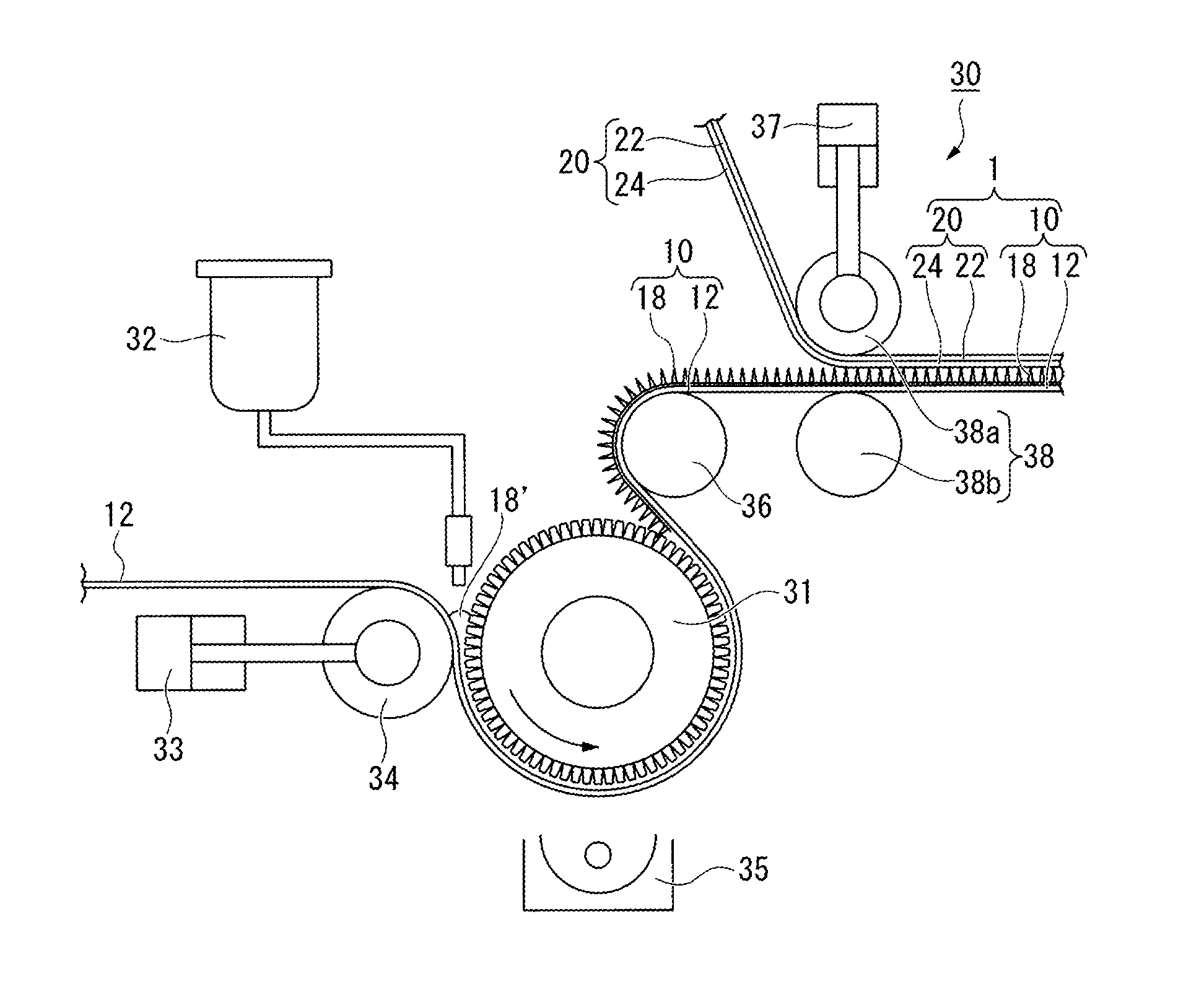
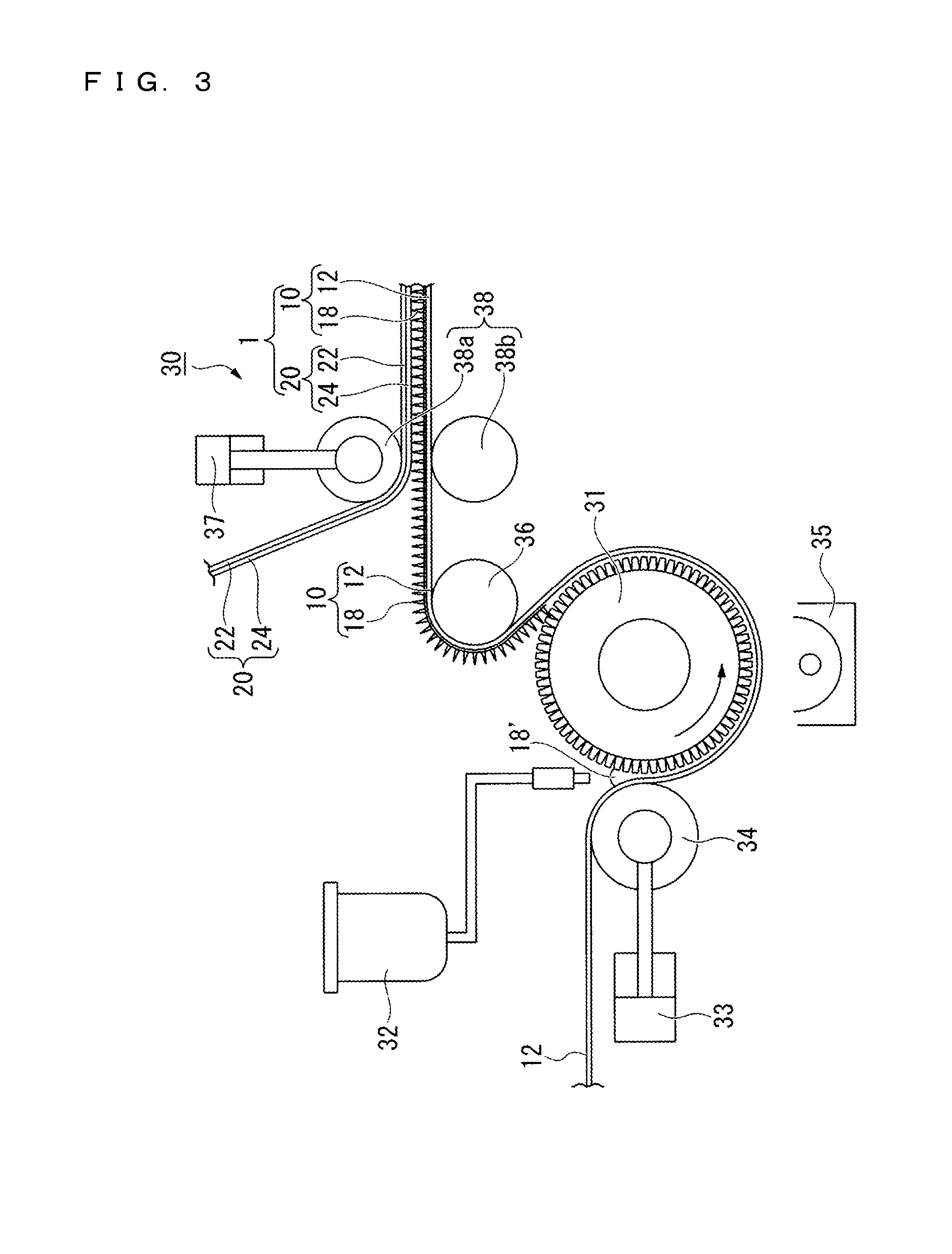
[0256]The roll-shaped mold was installed at the manufacturing device 30 illustrated in FIG. 3, an article 10 was manufactured by using the following method, and then...

example 2

[0263]A laminate structure was manufactured and evaluated in the same manner as Example 1 except that an adhesive film B (S-7 manufactured by DAIO PAPER CONVERTING CO., LTD.) having low-speed peeling strength (P) of 0.8 N / 25 mm and high-speed peeling strength (Q) of 0.25 N / 25 mm to an acrylic resin plate was used. The results are listed in Table 1.

example 3

[0264]A laminate structure was manufactured and evaluated in the same manner as Example 1 except that an adhesive film C (FM-355 manufactured by DAIO PAPER CONVERTING CO., LTD.) having low-speed peeling strength (P) of 1.0 N / 25 mm and high-speed peeling strength (Q) of 0.3 N / 25 mm to an acrylic resin plate was used. The results are listed in Table 1.


PUM

PropertyMeasurementUnit
Temperatureaaaaaaaaaa
Weightaaaaaaaaaa
Angleaaaaaaaaaa

Abstract

A laminate structure (1) includes an article (10) having a microrelief structure (16) on the surface thereof, and an adhesive film (20) being in contact with the microrelief structure (16)-side surface of the article (10), in which an average interval between projection portions (14) in the microrelief structure (16) is 400 nm or less, a low-speed peeling strength of the adhesive film (20) to an acrylic resin plate measured by a specific method based on JIS Z0237:2009 is 0.01 N / 25 mm or more and less than 2.5 N / 25 mm, and a ratio between a high-speed peeling strength and the low-speed peeling strength (high-speed peeling strength / low-speed peeling strength) of the adhesive film (20) to the acrylic resin plate is less than 2.

Description

TECHNICAL FIELD[0001]The present invention relates to a laminate structure, in which as for an article having a microrelief structure on a surface thereof, the surface on the side of the microrelief structure is protected by an adhesive film.[0002]This application claims priority under the benefit of JP 2011-284679 A, filed on Dec. 27, 2011 in Japan, the entire contents of which are incorporated herein by reference.BACKGROUND ART[0003]For various image display units, lens, show-windows, and the like, a degradation of visibility is a problem because the light of the sun, a lighting, and the like is reflected on the surface. Therefore, there are the occasions in which an anti-reflection film is attached on the surface.[0004]As an anti-reflection film, the film having a microrelief structure on the surface of a substrate is took noticed. Especially, the rugged microrelief structure arranged with a plurality of projections (projection portions) having an approximately cone shape, an app...

Claims


Application Information

Patent Timeline
IPC IPC(8): G02B1/11B32B27/06B32B3/00G01N19/04G01L5/00
CPCG02B1/111G01N19/04B32B2250/02B32B3/00B32B27/06G01L5/0033B32B7/06B32B7/12B32B27/08B32B2250/24B32B2255/10B32B2255/26B32B2307/408B32B2307/412B32B2307/538B32B2307/714B32B2307/728B32B2307/73B32B2307/748B32B2457/20B32B2551/00G02B1/118G02F1/133504Y10T428/24355
Inventor NAKAI, YUSUKEMAKINO, SHINJI
Owner MITSUBISHI RAYON CO LTD
Features
  • Generate Ideas
  • Intellectual Property
  • Life Sciences
  • Materials
  • Tech Scout
  • Unparalleled Data Quality
  • Higher Quality Content
  • 60% Fewer Hallucinations
Learn More