In-ceiling liquid desiccant air conditioning system

a liquid desiccant and air conditioning technology, applied in the field of ceiling liquid desiccant air conditioning systems, can solve the problems of large fan power and pressure drop across the packed bed, significant increase in overall energy costs, and large fan power and pressure drop, so as to achieve constant relative humidity and efficient dehumidification

Active Publication Date: 2014-12-18
COPELAND LP
View PDF3 Cites 30 Cited by
  • Summary
  • Abstract
  • Description
  • Claims
  • Application Information

AI Technical Summary

Benefits of technology

[0007]Provided herein are methods and systems used for the efficient dehumidification of an air stream using a liquid desiccant. In accordance with one or more embodiments, the liquid desiccant flows down the face of a thin support plate as a falling film and the liquid desiccant is covered by a membrane, while an air stream is blown over the membrane. In some embodiments, a heat transfer fluid is directed to the side of the support plate opposite the liquid desiccant. In some embodiments, the heat transfer fluid is cooled so that the support plate is cooled which in turn cools the liquid desiccant on the opposite side of the support plate. In some embodiments, the cool heat transfer fluid is provided by a central chilled water facility. In some embodiments, the thus cooled liquid desiccant cools the air stream. In some embodiments, the liquid desiccant is a halide salt solution. In some embodiments, the liquid desiccant is Lithium Chloride and water. In some embodiments, the liquid desiccant is Calcium Chloride and water. In some embodiments, the liquid desiccant is a mixture of Lithium Chloride, Calcium Chloride and water. In some embodiments, the membrane is a micro-porous polymer membrane. In some embodiments, the heat transfer fluid is heated so that th...

Problems solved by technology

Conventional vapor compression systems have only a limited ability to dehumidify and tend to overcool the air, oftentimes requiring energy intensive reheat systems, which significantly increases the overall energy costs because reheat adds an additional heat-load to the cooling coil or reduces the net-cooling provided to the space.
Absorption chillers however tend to be expensive both in terms of first cost and maintenance costs.
Such packed bed systems suffer from other disadvantages besides still having a carry-over risk: the high resistance of the packed bed to the air stream results in larger fan power and pressure drops across the packed bed, thus requiring more energy.
Furthermore, the dehumidification process is adiabatic, since the heat of condensation that is released during the absorption of water vapor into the desiccant has no place to go.
Warmer desiccant is also exp...

Method used


Image

  • In-ceiling liquid desiccant air conditioning system
  • In-ceiling liquid desiccant air conditioning system
  • In-ceiling liquid desiccant air conditioning system

Examples


Embodiment Construction

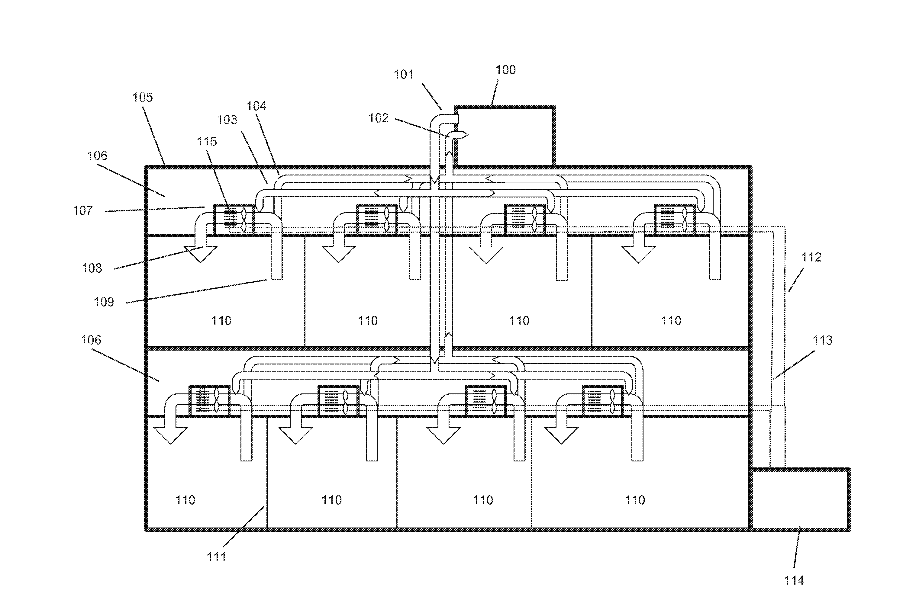
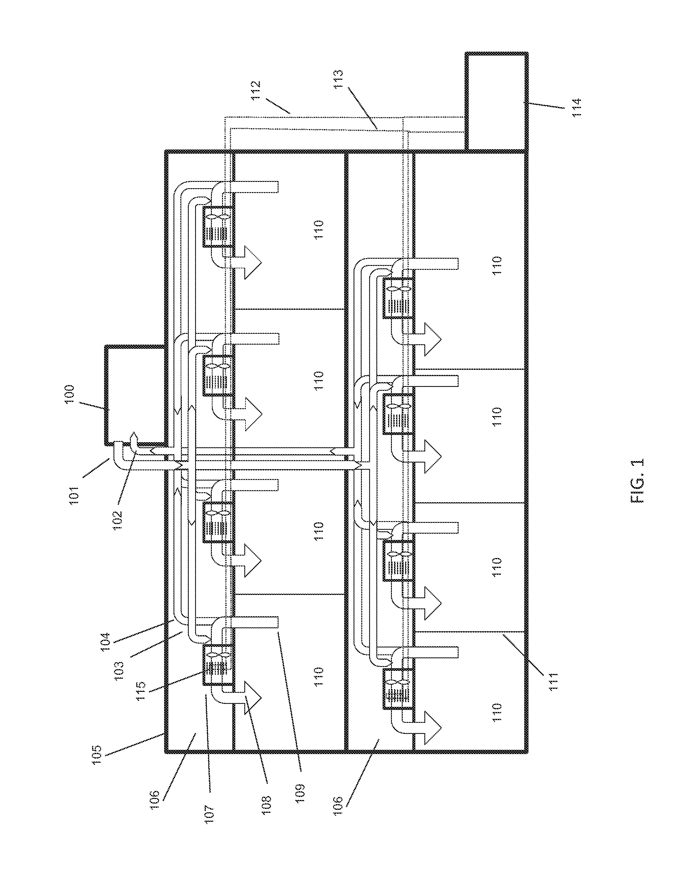
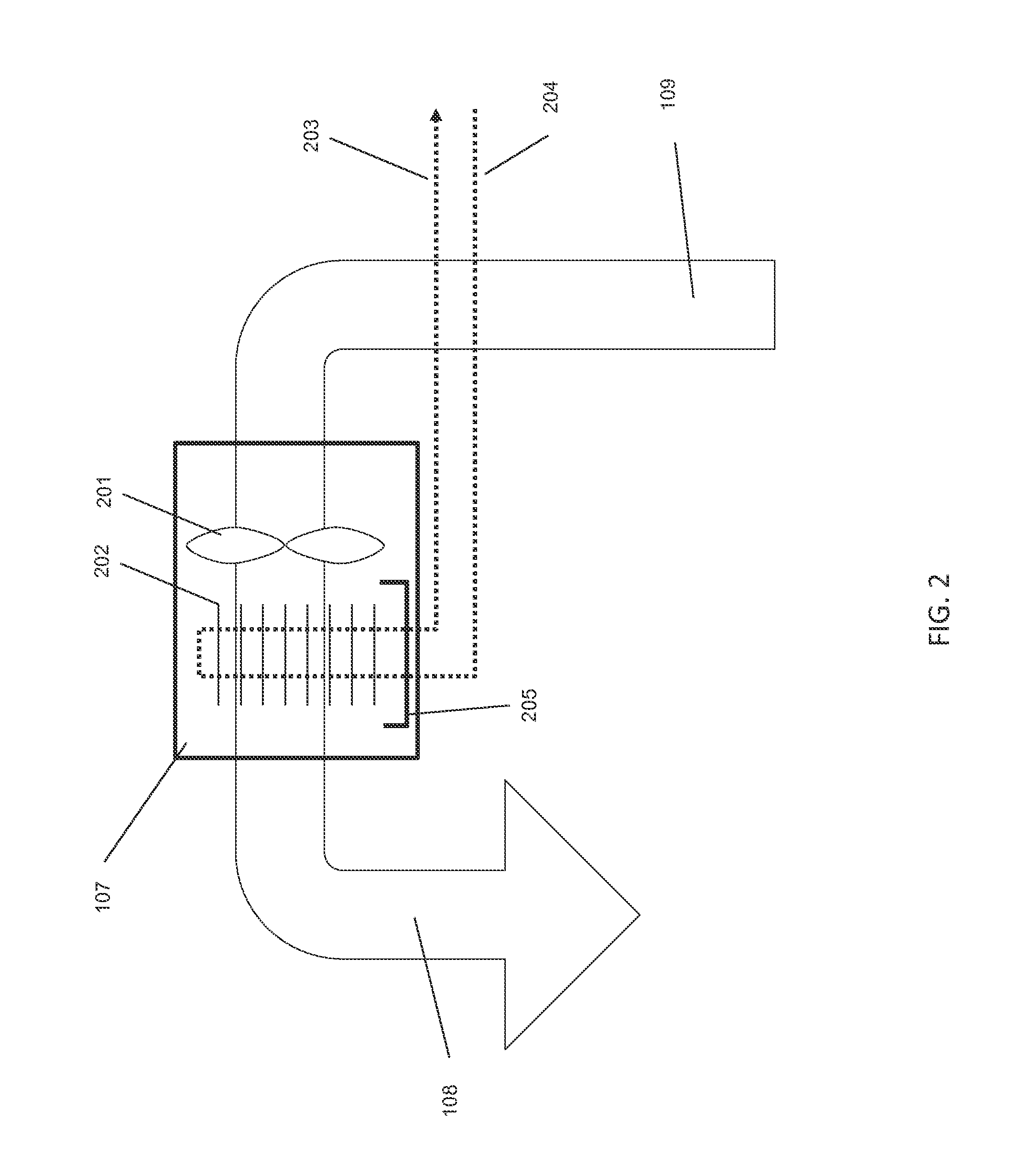
[0030]FIG. 1 depicts a typical implementation of an air conditioning system for a modern building wherein the outside air and the space cooling and heating are provided by separate systems. Such implementations are known in the industry as Dedicated Outside Air Systems or DOAS. The example building has two stories with a central air handling unit 100 on the roof 105 of the building. The central air handling unit 100 provides a treated fresh air stream 101 to the building that has a temperature that is usually slightly below room neutral conditions (65-70F) and has a relative humidity of 50% or so. A ducting system 103 provides air to the various spaces and can be ducted to the spaces directly or into a fan-coil unit 107 mounted in a suspended ceiling cavity 106. The fan-coil unit 107 draws air 109 from the space 110 and pushes it through a cooling or heating coil 115 mounted inside the fan-coil unit 107. The cooled or heated air 108 is then directed back into the space where it prov...


PUM


Abstract

An air-conditioning system includes a plurality of liquid desiccant in-ceiling units, each installed in a building for treating air in a space in the building. Dedicated outside air systems (DOAS) for providing a stream of treated outside air to the building are also disclosed.

Description

CROSS REFERENCE TO RELATED APPLICATION[0001]This application claims priority from U.S. Provisional Patent Application No. 61 / 834,081 filed on Jun. 12, 2013 entitled IN-CEILING LIQUID DESICCANT SYSTEM FOR DEHUMIDIFICATION, which is hereby incorporated by reference.BACKGROUND[0002]The present application relates generally to the use of liquid desiccant membrane modules to dehumidify and cool an air stream entering a space. More specifically, the application relates to the use of micro-porous membranes to separate the liquid desiccant from the air stream wherein the fluid streams (air, heat transfer fluids, and liquid desiccants) are made to flow turbulently so that high heat and moisture transfer rates between the fluids can occur. The application further relates to the application of such membrane modules to locally dehumidify spaces in buildings with the support of external cooling and heating sources by placing the membrane modules in or near suspended ceilings.[0003]Liquid desicca...

Claims


Application Information

Patent Timeline
IPC IPC(8): F24F3/14F25B15/00
CPCF24F3/1417F25B2315/00F25B15/00F24F2221/14F25B29/003F24F2003/1435F24F2003/1458
Inventor VANDERMEULEN, PETER F.
Owner COPELAND LP
Why Eureka
Try Eureka