Vibration damping device

a vibration damping and rubber technology, applied in the field can solve the problems of insufficient rigidity of the tube part, insufficient time and labor for manufacturing, complex structure of the outer bracket, etc., and achieve the effect of obtaining the vibration damping characteristics of each axis-perpendicular direction separately, reducing the number of vibration damping devices, and increasing the durability of the main rubber elastic body

Active Publication Date: 2014-12-18
TOYOTA JIDOSHA KK +1
View PDF31 Cites 15 Cited by
  • Summary
  • Abstract
  • Description
  • Claims
  • Application Information

AI Technical Summary

Benefits of technology

[0031]With the eighth mode, since the abutting surface of the main rubber elastic body and the retaining protruding part is ensured along a broad range on the circumference, falling out of the main rubber elastic body in the axial direction in relation to the outer bracket is more effectively prevented. In fact, by ensuring a large abutting surface area of the main rubber elastic body and the retaining protruding part during load input in the axial direction, stress during abutting is more greatly dispersed, and the durability of the main rubber elastic body is increased.
[0032]With the present invention, the outer bracket attached to the outer circumference surface of the main rubber elastic body is constituted to have the press fit metal fitting be press fit and fixed to the bracket main unit, and since the outer circumference end part of the main rubber elastic body is held between the abutting protruding part of the bracket main unit and the retaining protruding part of the press fit metal fitting in the axial direction, falling out of the main rubber elastic body from the outer bracket is effectively prevented. Furthermore, by the locking projection of the bracket main unit being inserted in the locking groove of the main rubber elastic body and locked in the circumference direction, relative rotation of the main rubber elastic body in relation to the outer bracket in the circumference direction is prevented, and it is possible to effectively obtain the vibration damping characteristics of each axis-perpendicular direction separately.
[0033]In fact, since the press fit metal fitting is a separate unit in relation to the bracket main unit, it is possible to set the die formed bracket main unit to a sufficient strength, and also to make it possible to form the retaining protruding part in advance on the press fit metal fitting single unit before press fitting to the bracket main unit, so it is possible to set the strength of the press fit metal fitting to also be sufficiently high.
[0034]Furthermore, the inner circumference surface of the bracket main unit and the inner circumference surface of the press fit metal fitting cooperate to be attached to the outer circumference surface of the main rubber elastic body. Therefore, it is possible to ensure sufficient attachment surface area of the outer bracket to the outer circumference surface of the main rubber elastic body while strongly fixing the press fit metal fitting to the bracket main unit by ensuring a large press fit margin.

Problems solved by technology

However, with the vibration damping device equipped with this kind of retaining structure noted in JP-A-11-257397, after the main rubber elastic body is housed in the outer bracket tube part, it is necessary to provide an overhang part using press processing, welding or the like on the axial end part of the tube part, and there was the risk that the outer bracket structure would become complex, and that this would require time and labor for manufacturing.
Also, when forming the tube part by bending a plate member equipped with the overhang part, if the plate member is too thin, there is the risk that the tube part rigidity will be insufficient, while on the other hand, if the plate member is too thick, there is the risk that it will be difficult to do the bending process of the overhang part.
Furthermore, since it is necessary to bend the overhang part in a state with the main rubber elastic body housed in the tube part, the rigidity is reduced by partially forming the overhang part on the circumference or the like so that the bending process is easy, but with this kind of structure, there were also cases when depending on the size of the input load, the shape of the main rubber elastic body or the like, it was difficult to have sufficient load bearing to prevent falling out of the main rubber elastic body in the axial direction.
However, this kind of structure shown in JP-A-2009-293766 can be used as long as it is a main rubber elastic body having a leg part for which the shape does not greatly affect the vibration damping characteristics, but for example when a concave groove of a size for which sufficient retaining action can be obtained is formed on the main rubber elastic body such as that noted in JP-A-11-257397, there was the problem of an adverse effect on the vibration damping characteristics and durability due to the decrease in rubber volume.
Meanwhile, when the concave groove is made smaller to suppress the effect on vibration damping characteristics and durability, the retaining action in the axial direction is insufficient, and there was the risk that the main rubber elastic body could fall out from the outer bracket during input of a large load.

Method used


Image

  • Vibration damping device
  • Vibration damping device
  • Vibration damping device

Examples


Embodiment Construction

[0045]Following, we will describe embodiments of the present invention while referring to the drawings.

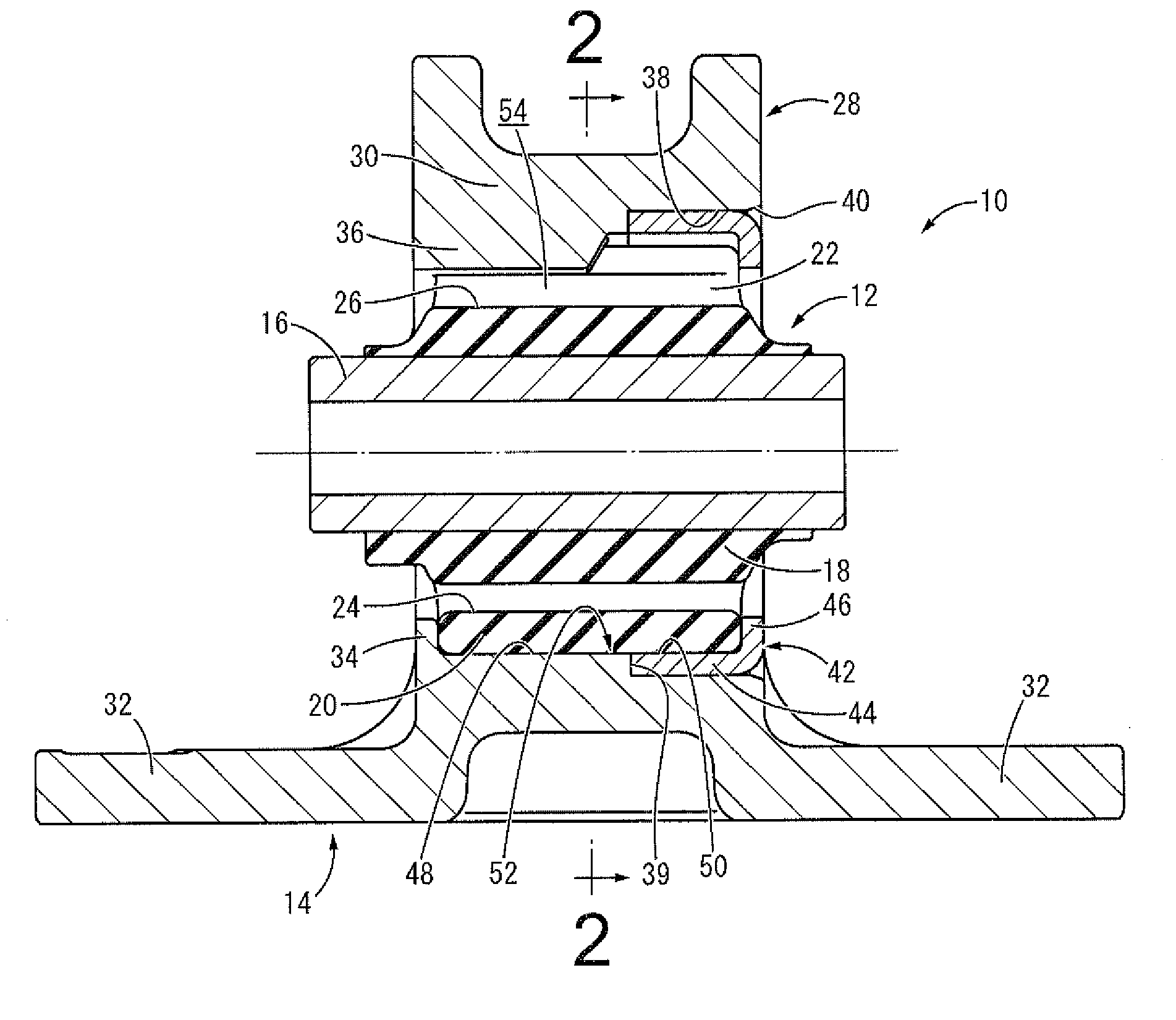
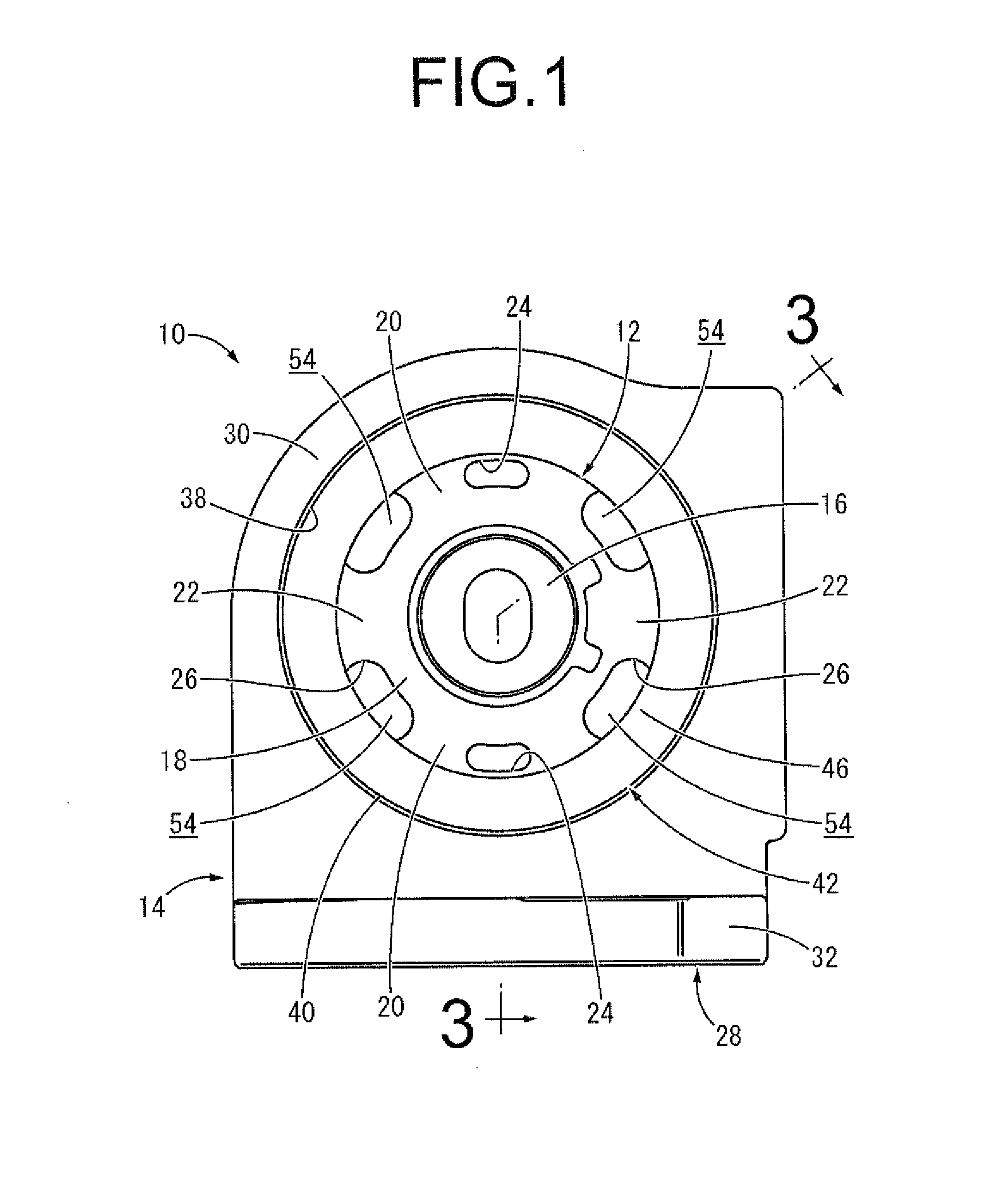
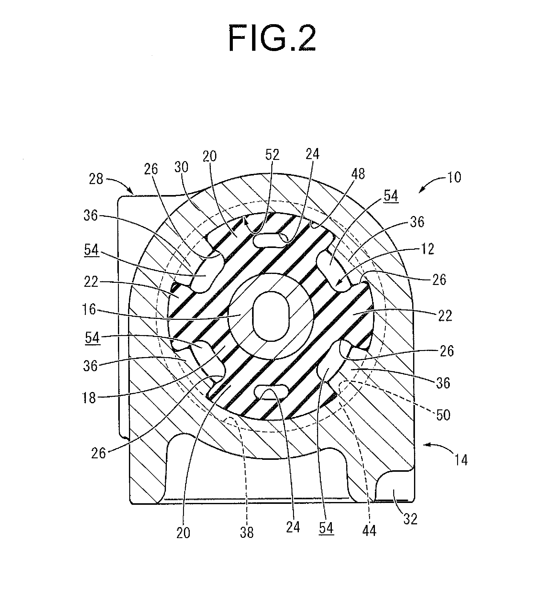
[0046]FIG. 1 through FIG. 3 show an engine mount 10 of an automobile as an embodiment of the vibration damping device according to the present invention. The engine mount 10 is equipped with a vibration damping device main unit 12 and an outer bracket 14. In the descriptions hereafter, as a general rule, the vertical direction means the vertical direction in FIG. 1 which is the vertical direction with the engine mount 10 mounted in the vehicle, the left-right direction means the left-right direction in FIG. 1, and the front-rear direction means the direction orthogonal to the paper surface in FIG. 1 which is the axial direction of the engine mount 10.

[0047]In more detail, as shown in FIG. 4 and FIG. 5, the vibration damping device main unit 12 has a structure with which a main rubber elastic body 18 is bonded by vulcanization to the outer circumference surface of an inner shaft mem...


PUM


Abstract

A vibration damping device including: an inner shaft member; a main rubber elastic body fixed to an outer circumference surface of the inner shaft member; and an outer bracket attached to an outer circumference surface of the main rubber elastic body. At least one locking projection formed to an inner circumference surface on a bracket main unit provided to the outer bracket is inserted and locked in a circumference direction in at least one locking groove formed on the outer circumference surface of the main rubber elastic body. The main rubber elastic body is held between axially opposed surfaces of an abutting protruding part formed on one axial end of the bracket main unit and a retaining protruding part formed on a press fit metal fitting press fit and fixed to another axial end of the bracket main unit.

Description

INCORPORATED BY REFERENCE[0001]The disclosure of Japanese Patent Application No. 2013-126276 filed on Jun. 17, 2013 including the specification, drawings and abstract is incorporated herein by reference in its entirety.BACKGROUND OF THE INVENTION[0002]1. Field of the Invention[0003]The present invention relates to a vibration damping device used for example as an automobile engine mount, a suspension member mount or the like.[0004]2. Description of the Related Art[0005]From the past, vibration damping devices have been known as one type of vibration damping connecting body or vibration damping support body that is interposed between members constituting a vibration transmission system and does vibration damping connection of these members to each other. As a vibration damping device, for example, as shown in Japanese Unexamined Patent Publication No. JP-A-11-257397, used is a constitution with which the vibration damping device main unit for which a main rubber elastic body is fixed...

Claims


Application Information

Patent Timeline
Patent Type & Authority Applications(United States)
IPC IPC(8): F16F15/08
CPCF16F15/08F16F1/3849F16F1/387F16F1/3835F16F1/3828F16F1/3873F16F1/3807
Inventor HIBI, SATORUSAIKI, AKIOYASUDA, TAKAYOSHIOHNISHI, MASAHIROMORI, KENTAROYOSHIDA, NOBUYAMIYA, HIROSHI
Owner TOYOTA JIDOSHA KK
Why Eureka
Try Eureka