Wireless power receiver system

a wireless power receiver and receiver technology, applied in the direction of transformers, inductances, transportation and packaging, etc., can solve the problems of reducing efficiency of resonators, limiting the use of mid-range systems that incorporate resonators, and wireless power supplies with resonators that typically do not operate efficiently with remote devices, etc., to achieve simple and effective wireless power receivers, improve efficiency, and facilitate incorporation

Active Publication Date: 2014-12-18
PHILIPS IP VENTURES BV
View PDF9 Cites 18 Cited by
  • Summary
  • Abstract
  • Description
  • Claims
  • Application Information

AI Technical Summary

Benefits of technology

[0013]The present invention provides a simple and effective wireless power receiver that can receive power from different types of wireless power supplies. In one embodiment, a single power receiver can be selectively reconfigured to function as a close-range receiver or a resonator for a mid-range receiver. In one embodiment, the principle receiver circuit and the supplemental receiver circuit are both capable of functioning as resonators, thereby providing the wireless power receiver the ability to adapt to different mid-range wire

Problems solved by technology

Although the use of resonators typically provides improved efficiency in mid-range environments, resonators can reduce efficiency when the wireless power supply and the remote device are too close.
This places a practical limi

Method used


Image

  • Wireless power receiver system
  • Wireless power receiver system
  • Wireless power receiver system

Examples


Embodiment Construction

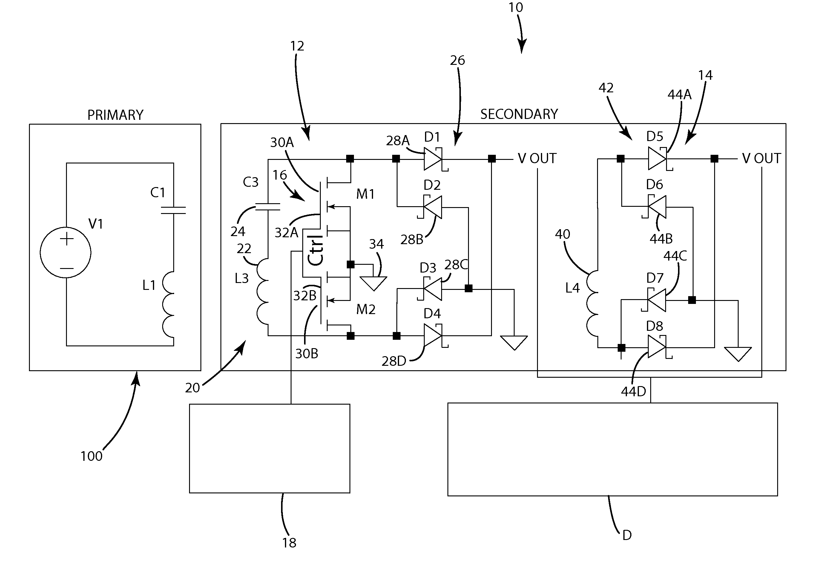
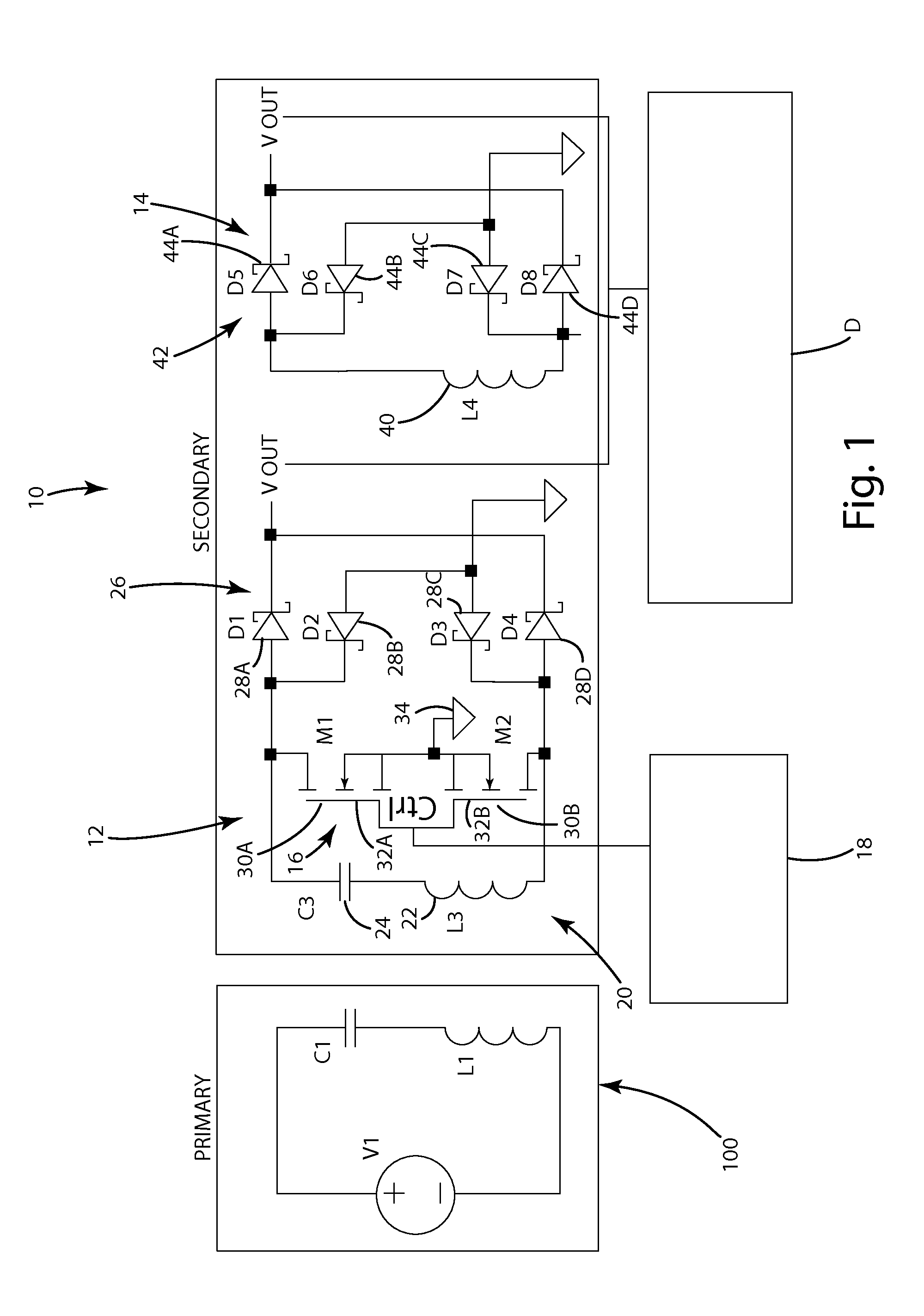
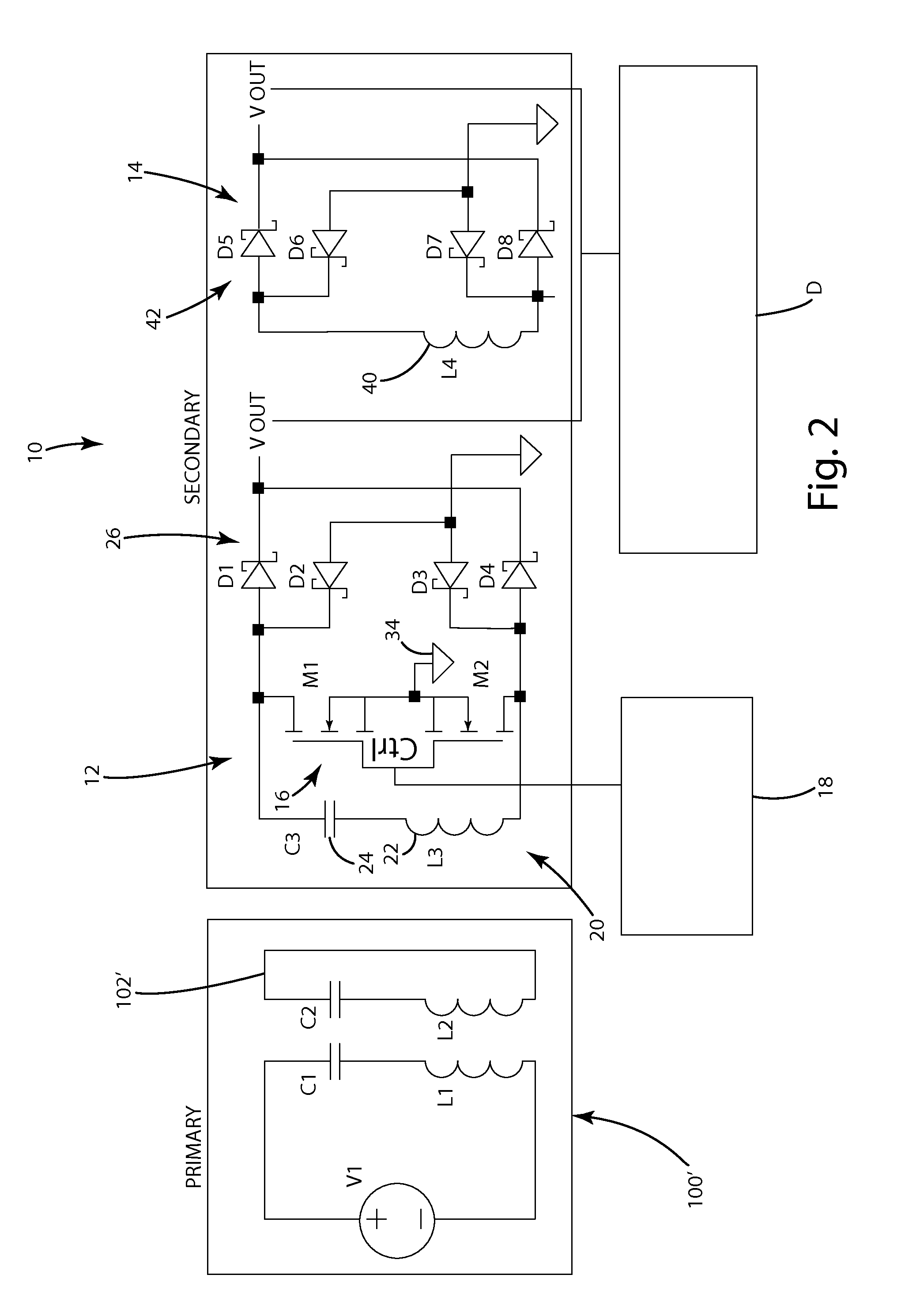
[0023]A wireless power receiver in accordance with an embodiment of the present invention is shown in FIGS. 1 and 2. The wireless power receiver 10 of this embodiment is configured to wirelessly receive power from a close-coupled wireless power supply 100 (see FIG. 1) or from a mid-range wireless power supply 100′ (see FIG. 2). The wireless power receiver 10 is coupled to a remote device D so that it can supply the wirelessly-received power to the remote device D. The wireless power receiver 10 is capable of selectively being reconfigured to operate in close-coupled mode or in mid-range mode to allow it to efficiently receive power from different types of wireless power supplies 100, 100′. The wireless power receiver 10 of this embodiment generally includes a principle receiver circuit 12, a supplemental receiver circuit 14 and a controller 18 for controlling operation of the wireless power receiver 10. In this embodiment, the principle receiver circuit 12 and the supplemental recei...


PUM


Abstract

A wireless power receiver capable of receiving wireless power from close-coupled and mid-range wireless power supplies. The wireless power receiver includes a principal and supplemental receiver circuits. The principle receiver circuit is adjustable to operate in a close-coupled mode or a resonator mode. In close-coupled mode, the principle receiver circuit is coupled to the power input of a remote device and functions as the principle power source. In resonator-mode, the principle power circuit is electrically disconnected/isolated from the remote device and forms a closed resonant loop to function as a resonator that amplifies an electromagnetic field from a mid-range wireless power supply. The supplemental receiver circuit is coupled to the power input of the remote device and is configured to receive wireless power from the resonator and function as the power source when the principle receiver circuit is in the resonator mode.

Description

BACKGROUND OF THE INVENTION[0001]The present invention relates to wireless power transfer, and more particularly to systems for wirelessly receiving power from a wireless power supply.[0002]The use of wireless power supply systems continues to grow. The most common wireless power supply systems use electromagnetic fields to wirelessly transfer power from a wireless power supply to wireless power receiver associated with a remote device, such as a cell phone, a smart phone, a media player or other electronic device. There are a number of different types of wireless power supply systems. For example, many conventional systems use a primary coil in the wireless power supply and secondary coil in the wireless power receiver of the remote device. The primary coil generates an electromagnetic field that emanates from the wireless power supply. The wireless power receiver includes a secondary coil that can be placed within the electromagnetic field generated by the primary coil. When the r...

Claims


Application Information

Patent Timeline
IPC IPC(8): H02J5/00H04B5/00H02J7/02
CPCH02J5/005H04B5/0075H02J7/02H02M3/3384H04B5/0037H04B5/0081H02J50/12H02J7/00712Y02B70/10H02J50/40
Inventor NORCONK, MATTHEW J.MOORE, COLIN J.TAYLOR, JOSHUA B.
Owner PHILIPS IP VENTURES BV
Why Eureka
Try Eureka