Method and assembly for soldier pile retaining wall leveling and erosion control

a technology of retaining wall and leveling and assembly, which is applied in the direction of artificial islands, construction, marine site engineering, etc., can solve the problems of premature failure of the shore wall, erosion to occur under the shore wall, and limited life expectancy of the installation, so as to prevent erosion, delaying the erosion process, and pleasing aesthetics

Inactive Publication Date: 2014-12-18
POFF JACK ALLEN
View PDF4 Cites 6 Cited by
  • Summary
  • Abstract
  • Description
  • Claims
  • Application Information

AI Technical Summary

Benefits of technology

This patent describes a way to make sure a new layer of material stays upright on top of water without being washed away during high tides or other events. It uses a special tool designed like a wedgeshaped knife that slices into the bottom of the ocean floor. Once this happens, the material used to build the structure levels out, making it easier to place things on top of it. This results in a smooth and stable surface that helps keep the water calm and prevents damage caused by waves and currents. Overall, this technique makes it possible to create better structures on the sea floor than traditional methods.

Problems solved by technology

The technical problem addressed in this patent text needs to be identified by a senior R&D person who can read it easily without adding any new information.

Method used


Image

  • Method and assembly for soldier pile retaining wall leveling and erosion control
  • Method and assembly for soldier pile retaining wall leveling and erosion control
  • Method and assembly for soldier pile retaining wall leveling and erosion control

Examples


Embodiment Construction

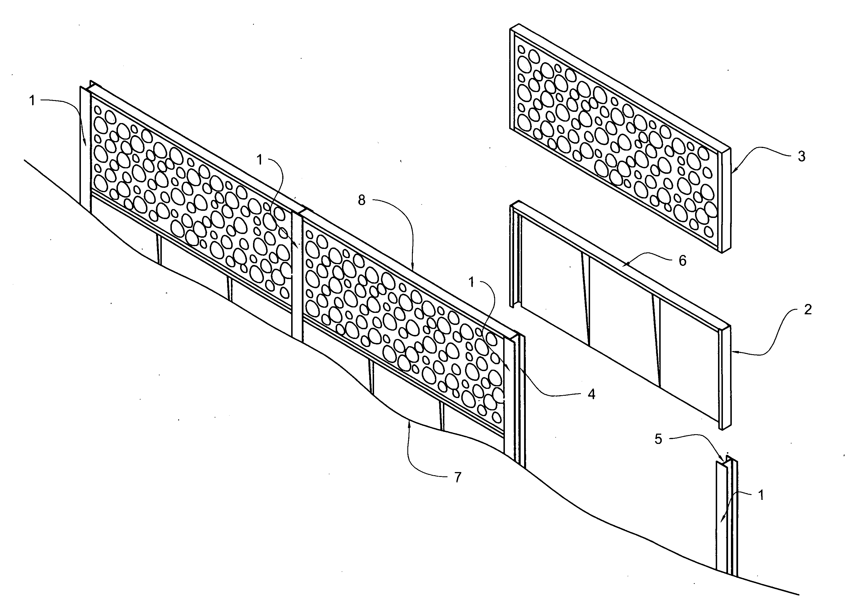
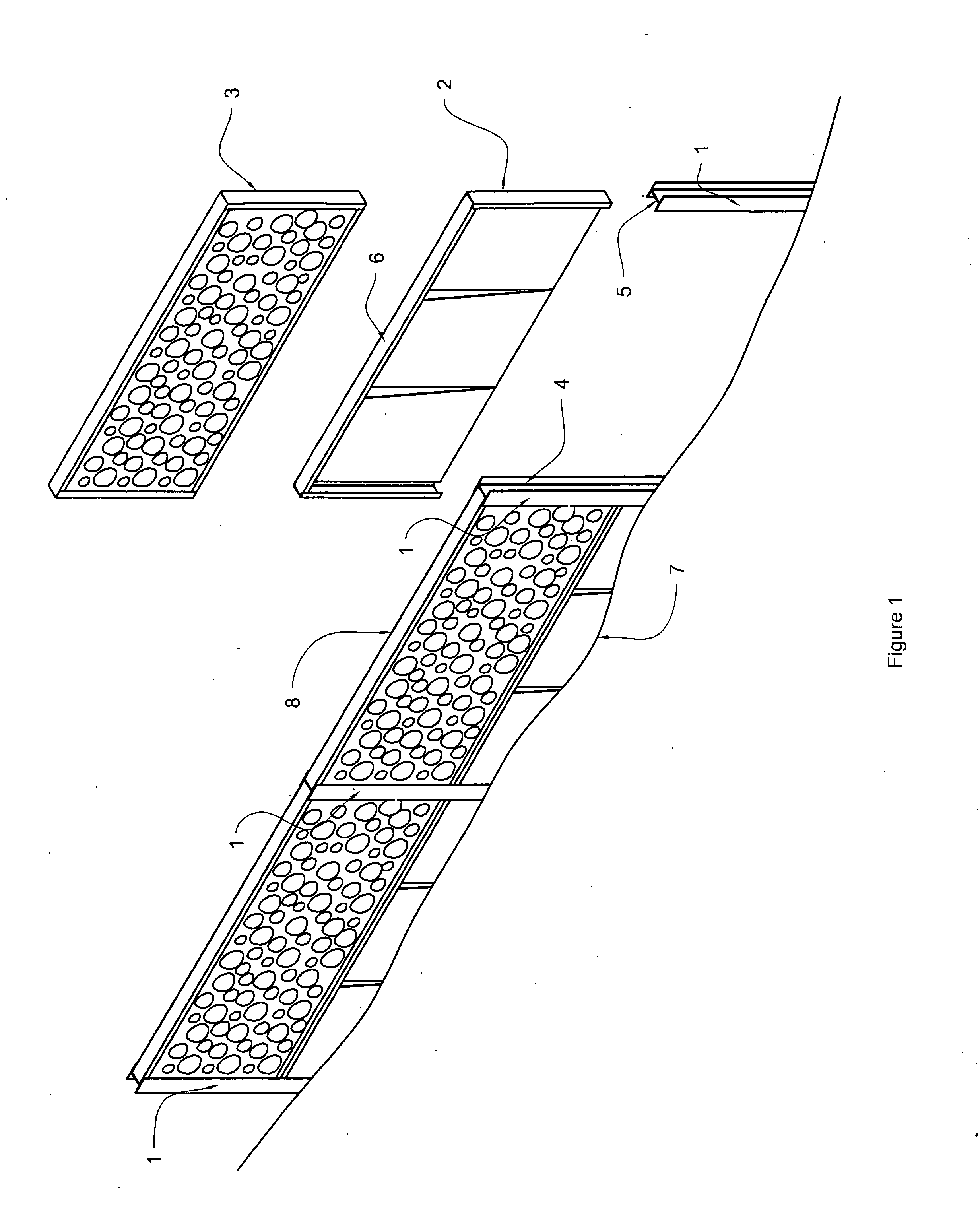
[0013]FIG. 1 illustrates one embodiment of the novel shore wall or retaining wall of the invention intended for installation along the periphery of a body of water. A plurality of vertical soldier pilings (1) are driven or pounded into the bed of the body of water along a longitudinal center line with uniform spacing equivalent to the longitudinal dimension of the shore wall base element assembly (2) and lagging panels (3). The opposing transverse slots (4-5) of the vertical soldier pilings are equivalent width to the width of the framing element (6) of the shore wall base element assembly. The side edge framing element is slotted into the receiving slot of the soldier pile which is an I-beam in the preferred embodiment. After the shore wall base element is inserted between adjacent soldier pilings, the shore wall base element is driven or pounded into the bed of the body of water (7). The same mechanism is repeated for a plurality of shore wall base elements which are driven or pou...


PUM


Abstract

A method and assembly are disclosed for building a soldier pile shore wall or soldier pile retaining wall. The method and assembly are designed to permit the shore wall to be leveled along the bed of a body of water, whether the bed of the body of water is level or not level. Simultaneously, the method and assembly prevent erosion of the bed of the body of water in the vicinity of the assembly, extending the life-span of the shore wall, and enabling maintenance of the shore wall to be performed by permitting the assembly to be re-embedded in the bed of the body of water and re-leveled at the time when erosion eventually does occur.

Description


Claims


Application Information

Patent Timeline
Owner POFF JACK ALLEN
Why Eureka
Try Eureka