Centrifugal compressor

Inactive Publication Date: 2014-12-18
MITSUBISHI HEAVY INDUSTIES COMPRESSOR CORP
View PDF4 Cites 12 Cited by
  • Summary
  • Abstract
  • Description
  • Claims
  • Application Information

AI Technical Summary

Benefits of technology

[0023]According to the centrifugal compressor of the first invention, since θ−α>0°, skewing of the velocity distribution of the gas is eliminated, and accordingly a decrease in amount of static pressure recovery is suppressed. Therefore, a higher efficiency of the entire compressor can be achieved.
[0024]According to the centrifugal compressor of the se

Problems solved by technology

However, the above-described apparatuses require that new mechanisms should be provided in

Method used


Image

  • Centrifugal compressor
  • Centrifugal compressor
  • Centrifugal compressor

Examples


embodiment 1

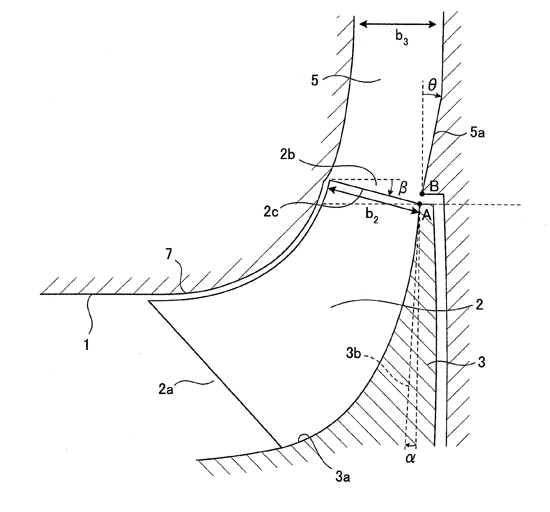
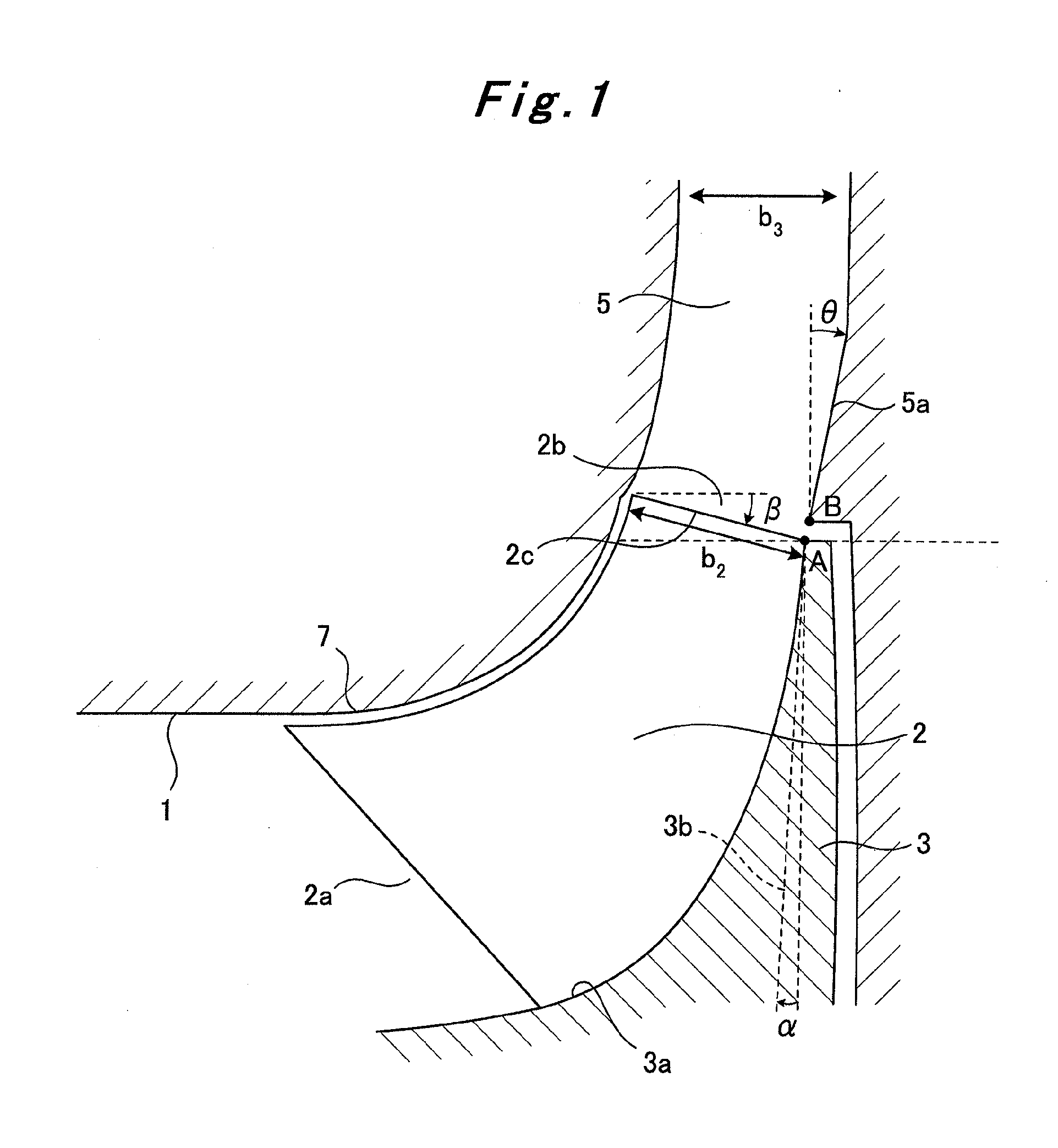
[0034]An apparatus according to Embodiment 1 of the present invention will be described by use of FIG. 1. The apparatus mainly includes a suction inlet 1, an impeller 2, a hub 3, a rotary shaft 4, a diffuser 5, and a scroll 6, as in the case of the conventional centrifugal compressor. The impeller 2 is connected to the rotary shaft 4 via the hub 3. In addition, the diffuser 5 is provided downstream of the impeller 2, has a flow passage directed in a direction away from the rotary shaft 4, and has an outlet directed in a radial direction in a meridian plane. Moreover, the scroll 6 is provided downstream of the diffuser 5, and communicates with an outlet of the diffuser 5. Note that the rotary shaft 4 and the scroll 6 are not shown in FIG. 1, but are assumed to be the same as those of the conventional technical.

[0035]Furthermore, like the conventional technique, the suction inlet 1 plays a role of guiding a gas to the impeller 2. The centrifugal compressor is configured such that the ...

embodiment 2

[0044]An apparatus according to Embodiment 2 of the present invention is one obtained by improving the apparatus according to Embodiment 1. FIG. 4 shows differences between the apparatus according to Embodiment 1 and the present apparatus. In the apparatus according to Embodiment 1, since the diffuser inlet hub-side line 5a is a straight line, directing the outlet of the diffuser 5 in the radial direction requires that the angle of the diffuser 5 has to be changed at a certain portion. As a result, as shown in FIG. 4, a stagnation region 11 where the flow of the gas stagnates is formed. Shear stress acts between the gas stagnating in the stagnation region 11 and the flowing gas, leading to a possibility of occurrence of an energy loss. The present apparatus reduces the stagnation region 11.

[0045]As in the case of the apparatus according to Embodiment 1, as shown in FIG. 3, the present apparatus mainly includes a suction inlet 1, an impeller 2, a hub 3, a rotary shaft 4, a diffuser 5...


PUM


Abstract

A centrifugal compressor for which θ−α>0° and 0°<θ<34°, when the angle formed by a diffuser inlet hub-side line (5a) and the radial direction at a point B in the meridian plane is θ, and the angle formed by a tangent line (3b) and the radial direction at a point A of an impeller hub-side line (3a) nearest the inlet of the diffuser (5) is α. Thus, skewing of the velocity distribution of a gas within the diffuser of the centrifugal compressor is eliminated.

Description

TECHNICAL FIELD[0001]The present invention relates to a centrifugal compressor, and particularly to a centrifugal compressor with a large flow rate.BACKGROUND ART[0002]For improving the performances of products such as superchargers, gas turbines, and industrial compressors, it is a critical issue to increase the flow rate. Increasing the flow rate of a centrifugal compressor means to increase the discharge flow rate of a compressor with the same shell size, and further of an impeller with the same outer diameter.[0003]One of the problems associated with the increase in flow rate is a decrease in efficiency. For this reason, a technique of increasing the flow rate while suppressing the decrease in efficiency is industrially very significant.[0004]A conventional centrifugal compressor will be described by using FIG. 6. The centrifugal compressor mainly includes a suction inlet 1, an impeller 2, a hub 3, a rotary shaft 4, a diffuser 5, and a scroll 6.[0005]The impeller 2 is connected ...

Claims


Application Information

Patent Timeline
IPC IPC(8): F04D29/44F04D17/10
CPCF04D17/10F04D29/444F04D29/284F04D29/441
Inventor YAMASHITA, SHUICHI
Owner MITSUBISHI HEAVY INDUSTIES COMPRESSOR CORP
Why Eureka
Try Eureka