
Pest electrocution device

Inactive Publication Date: 2014-12-25
RATEL
View PDF1 Cites 7 Cited by
  • Summary
  • Abstract
  • Description
  • Claims
  • Application Information

AI Technical Summary

Benefits of technology

The present invention is an electrocution device that has very few movable parts, making it reliable and easy to maintain. The device can be installed from the surface in manholes that are not accessible for personnel, and it can also be easily removed for inspection or service purposes. This makes inspection and service possible above ground, improving efficiency and reliability.

Problems solved by technology

The number of pests and in particular rodents such as rats and mice is an ever increasing problem.
This results in an ever increasing number of rats increasing the problems associated with rats such as spread of disease, unhygienic conditions, increased deterioration of sewer systems etc.
A problem with the pest extermination devices relying on the use of a poison is the fact that the rats have a tendency to grow immune or resistant against the poison such that after a while new poisons have to be implemented or developed, and the effective usefulness of these devices is usually relatively short-term.
The type of device which skewers the rat is very inhumane in that unless the rat is positioned precisely relative to the skewers, the rat will be maimed and will hopefully eventually die from its injuries.
Otherwise the rat will be handicapped, but still be a pest in the sewer system.
One problem, however, is the fact that the sewer systems usually present a very moist / humid and aggressive environment and that the electronics and mechanics implemented in these devices are relatively sensitive to the environment in the sewer system and as such will experience a shorter life expectancy than expected.

Method used


Image

  • Pest electrocution device
  • Pest electrocution device
  • Pest electrocution device

Examples


Embodiment Construction

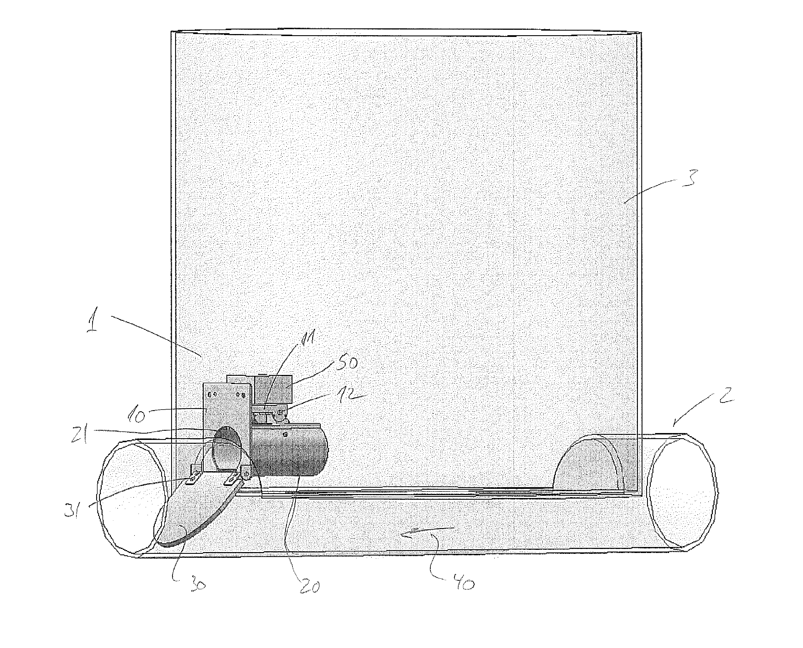
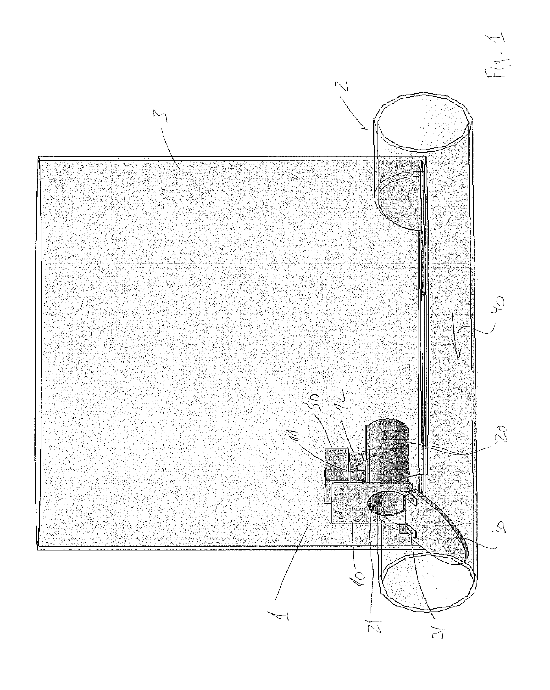
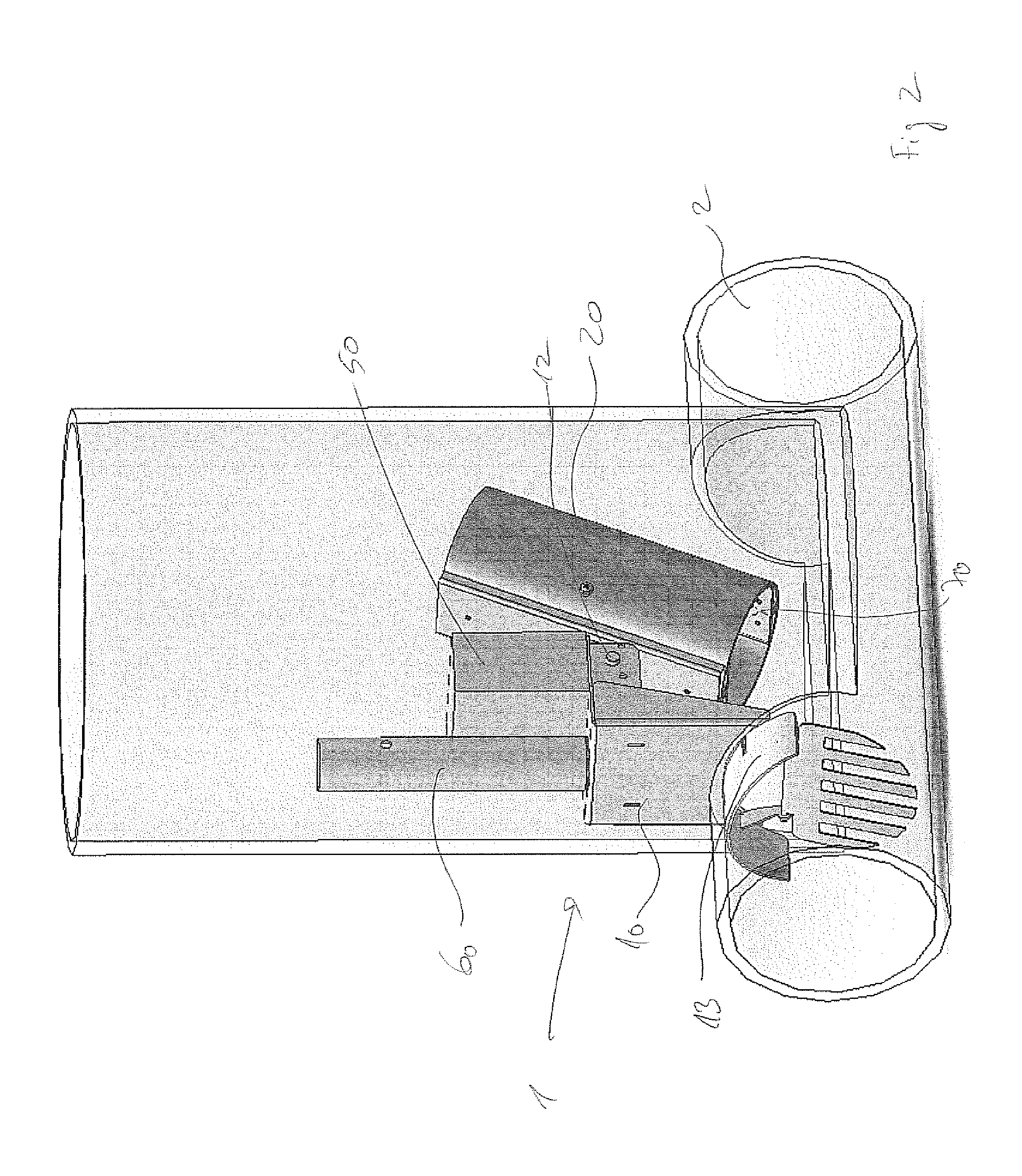
[0010]The invention addresses this need by providing a pest electrocution device suitable to be mounted in a pipe or conduit, wherein the electrocution device comprises a ramp hingely attached to a chassis, which chassis has means to be fastened to said pipe or conduit, where said chassis further comprises a chassis arm, and a tunnel element, which tunnel element is pivotably fastened to said chassis arm, and where the tunnel element in a first position extends to an upper end of said ramp, such that a pest travelling up the ramp can enter the tunnel element at a first end, where activating means are provided inside the tunnel element, which activation means activate at least three electrodes by supplying electrical current to said electrodes arranged as separate floor plates in the tunnel, such that after activation and a predetermined period of time, the tunnel element pivots the first end downwards into a second position, in which second position the electrocuted pest slides out ...


PUM

PropertyMeasurementUnit
Timeaaaaaaaaaa
Electric potential / voltageaaaaaaaaaa

Abstract

Pest electrocution device, suitable to be mounted in a pipe (2) or conduit, wherein the electrocution device comprises a ramp (30) hingely attached to a chassis (10), which chassis has means to be fastened to said pipe or conduit, where said chassis further comprises a chassis arm (11), and a tunnel element (20), which tunnel element is pivotably fastened to said chassis arm, and where the tunnel element in a first position extends to an upper end of said ramp, such that a pest travelling up the ramp can enter the tunnel element at a first end, where activating means are provided inside the tunnel element, which activation means activate at least three electrodes (70, 71, 72) by supplying electrical current to said electrodes arranged as separate floor plates in the tunnel, such that after activation and a predetermined period of time, the tunnel element pivots the first end downwards into a second position, in which second position the electrocuted pest slides out of the tunnel element, after which the tunnel element is pivoted back in its first position.

Description

FIELD OF THE INVENTION[0001]The present invention relates to a pest electrocution device as well as a method of electrocuting a pest using such a device, and a method for mounting the novel and inventive device in a pipe or conduit.BACKGROUND OF THE INVENTION[0002]The number of pests and in particular rodents such as rats and mice is an ever increasing problem. In particular, rats have adapted to life in the sewer systems to such a degree that the old and deteriorating sewer systems present in many cities around the world provides premium habitat for rats. This results in an ever increasing number of rats increasing the problems associated with rats such as spread of disease, unhygienic conditions, increased deterioration of sewer systems etc.[0003]Consequently, a number of devices has been developed and deployed in order to try to minimize both the spread of rats in the sewer system and different ways of exterminating the rats present in the sewer system.[0004]In order to extermina...

Claims


Application Information

Patent Timeline
IPC IPC(8): A01M23/38
CPCA01M23/38Y10T29/49947
Inventor KNUDSEN, HANSTHIIM, CHRISTIAN
Owner RATEL
Learn More