

Screw-driven lifting platform
- Summary
- Abstract
- Description
- Claims
- Application Information
AI Technical Summary
Benefits of technology
Problems solved by technology
Method used
Image

Examples
embodiment 1
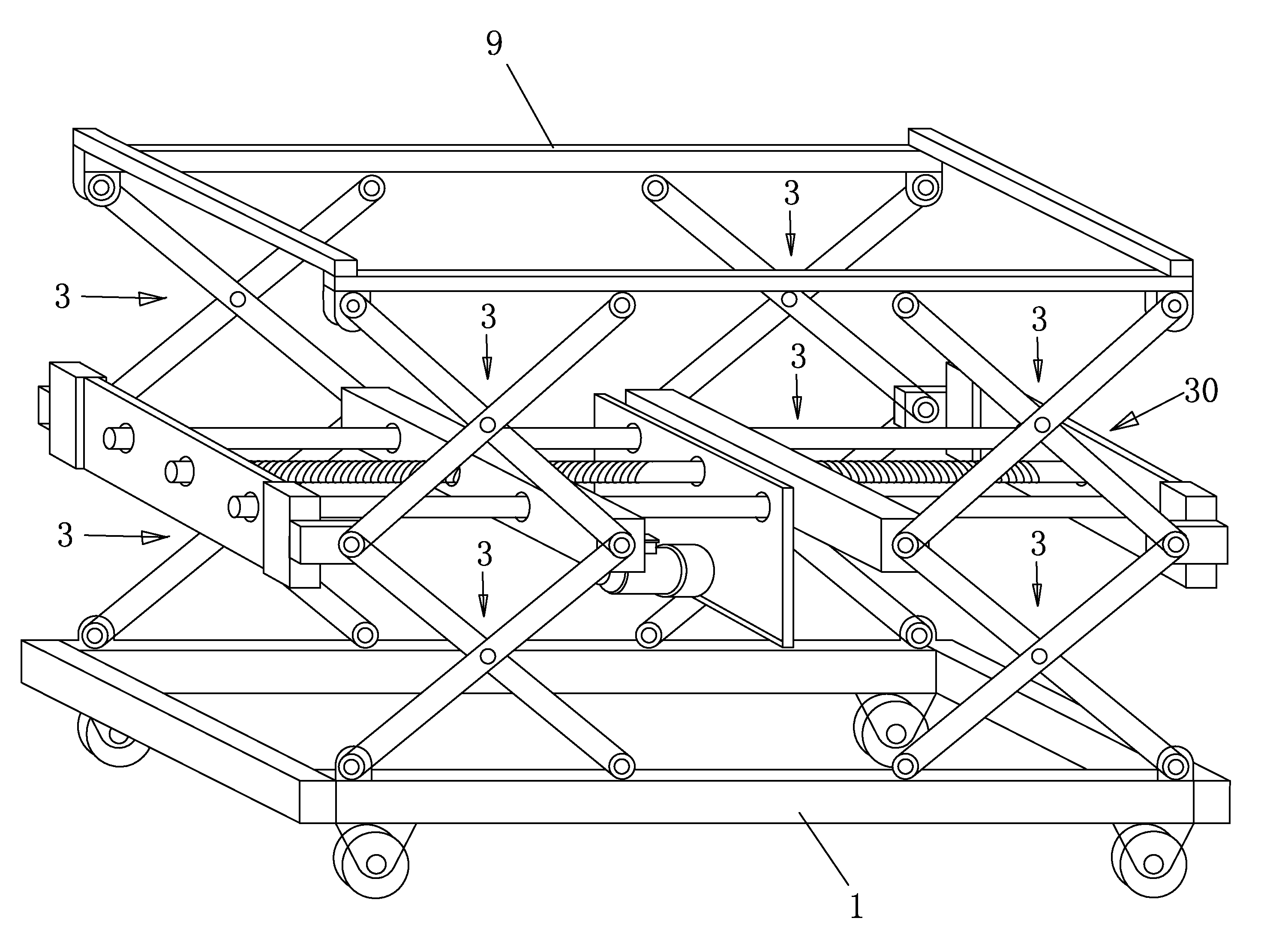
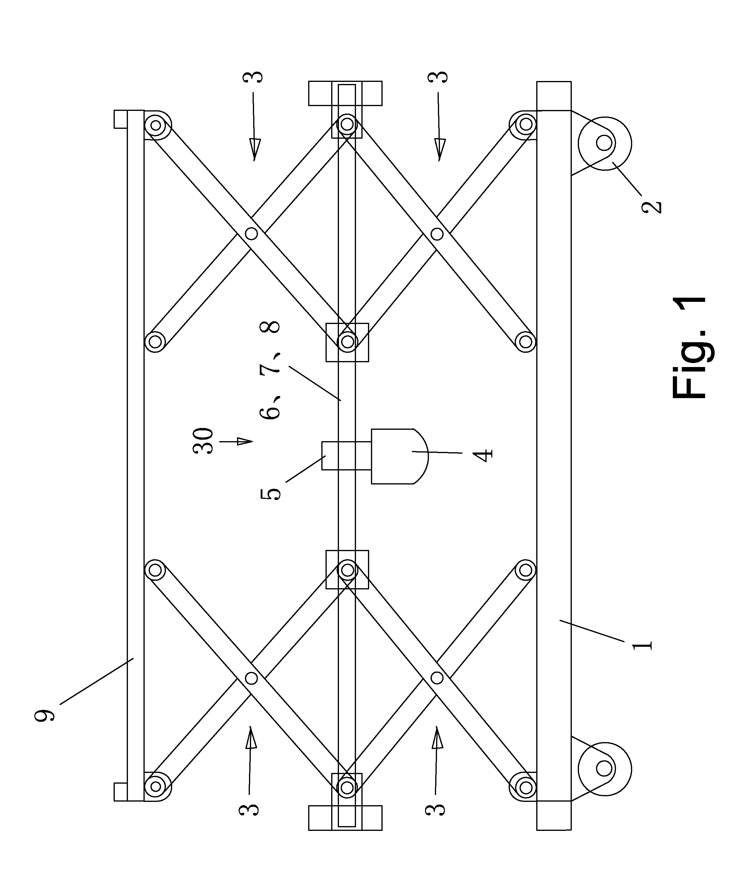
[0044]As shown in FIG. 1-3, the screw-driven lifting platform mainly comprises a base 1, a left and a right group of X-shaped connecting rods 3, a horizontal lifting platform 30 and a horizontal lifting working plane 9 and etc. The key technique is driving two groups of X-shaped connecting rods to move by the left-and-right screw thread rod, so as to realize a horizontal lifting function.
[0045]Structure of the base 1 is a frame in a shape of a closed rectangular. Two borders on the surface of the frame serve as guide rails 11. Hinge holes 12 for connecting with the X-shaped connecting rods 3 are provided above four corners of the frame. Walking wheels 2 are provided below the four corners of the frame.
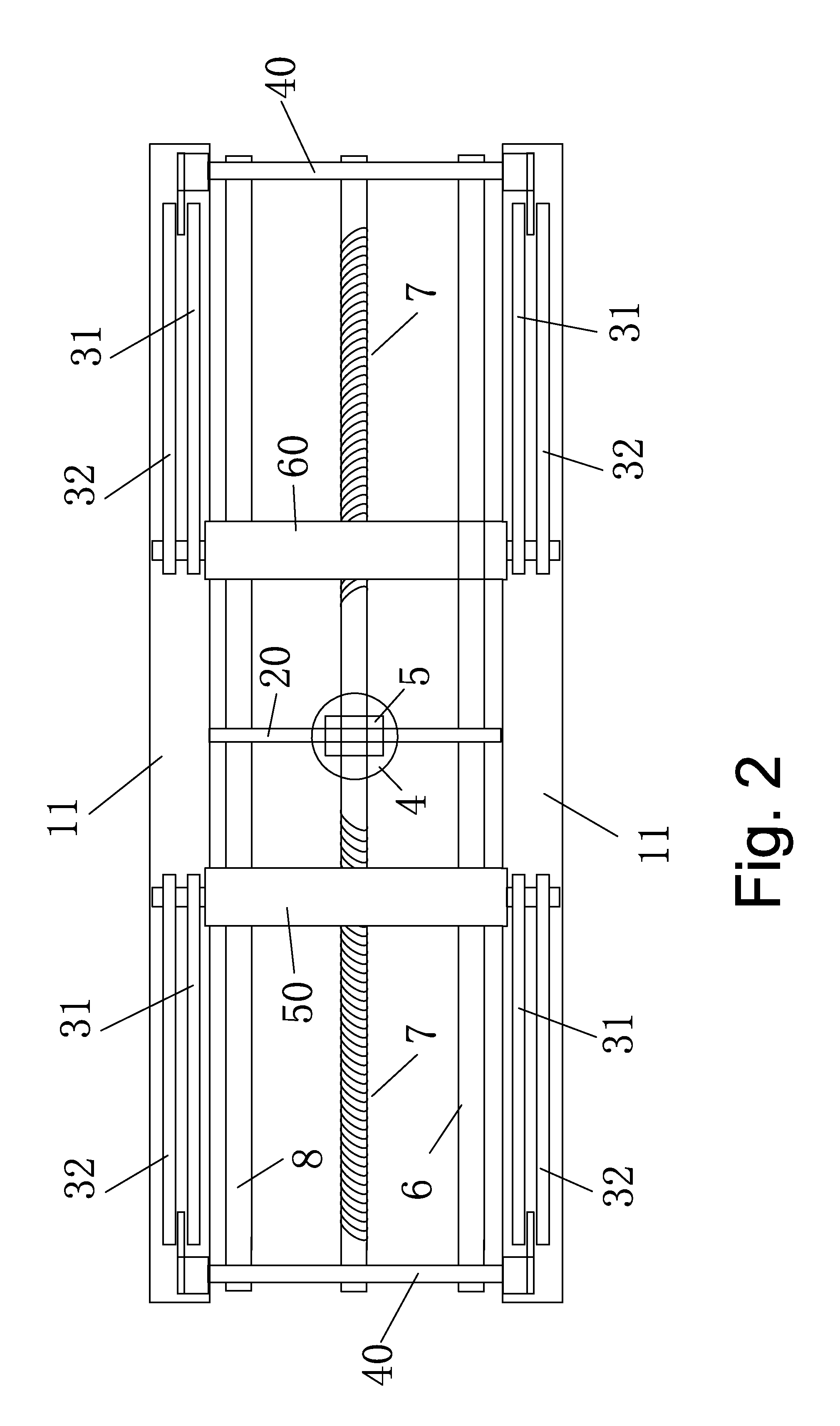
[0046]The left and the right group of X-shaped connecting rods 3 comprise a stabilizing arm 31 and a driving arm 32. The stabilizing arm 31 and the driving arm 32 are crossed and hinged together in middle portions thereof.
[0047]The horizontal lifting platform 30 comprises a left-and-ri...
embodiment 2
[0060]As shown in FIG. 1 and FIG. 6, a horizontal lifting working plane 9 is added above the horizontal lifting platform 30. The horizontal lifting working plane 9 is connected with the horizontal lifting platform 30 via two groups of (a left group and a right group) and four in total X-shaped connecting rod 3.
[0061]The upper ends of the four driving arms are hinged on hinge holes 12 below four corners of the horizontal lifting working plane 9, and the lower ends of the four driving arms are respectively hinged on the hinge shafts 34 on the left-hand driving guide block 50 and the right-hand driving guide block 60. The lower ends of the four stabilizing arms are hinged on the hinge holes 12 on fixing block 40 for end portion of the guide rod, the upper ends of the four stabilizing arms are supporting on guide rails 11 on the horizontal lifting working plane 80, and move on the guide rails 11. Middle portions of each stabilizing arm 31 and the driving arm 32 are hinged together via t...
PUM
 Abstract
Description
Claims
Application Information