Arrangement of a wheel hub connected to a constant velocity joint provided with a low friction seal device

a constant velocity joint and seal device technology, applied in the direction of mechanical devices, couplings, transportation and packaging, etc., can solve the problems of high cost, large bulk, and complex ep2043880 encapsulation, and achieve excellent fluid-tight seal, easy encapsulation and mounting, and strong reduction of friction between relatively mobile parts

Active Publication Date: 2014-12-25
AB SKF
View PDF3 Cites 9 Cited by
  • Summary
  • Abstract
  • Description
  • Claims
  • Application Information

AI Technical Summary

Benefits of technology

[0012]Thereby, a compact assembly structure is obtained of the device, with both reduced axial and radial bulks, which structure is easy to embody and mount, without subjecting the parts with substantial axial length to buckling stresses. An excellent fluid-tight seal is equall

Problems solved by technology

The solution according to EP2043880 is costly, complex to embody, and creates large bulks, both in radial and axial direction.
Such a

Method used


Image

  • Arrangement of a wheel hub connected to a constant velocity joint provided with a low friction seal device
  • Arrangement of a wheel hub connected to a constant velocity joint provided with a low friction seal device

Examples


Embodiment Construction

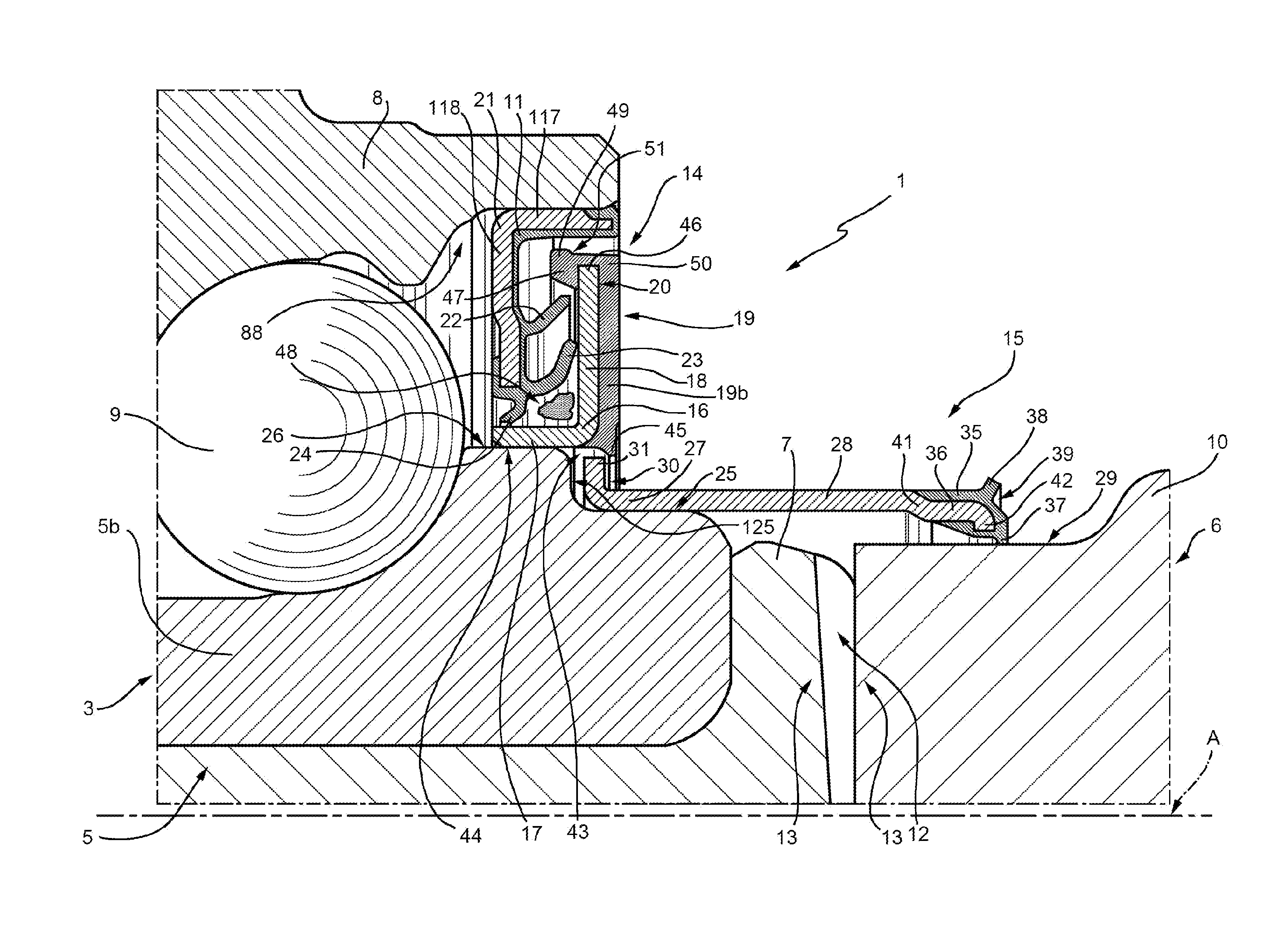
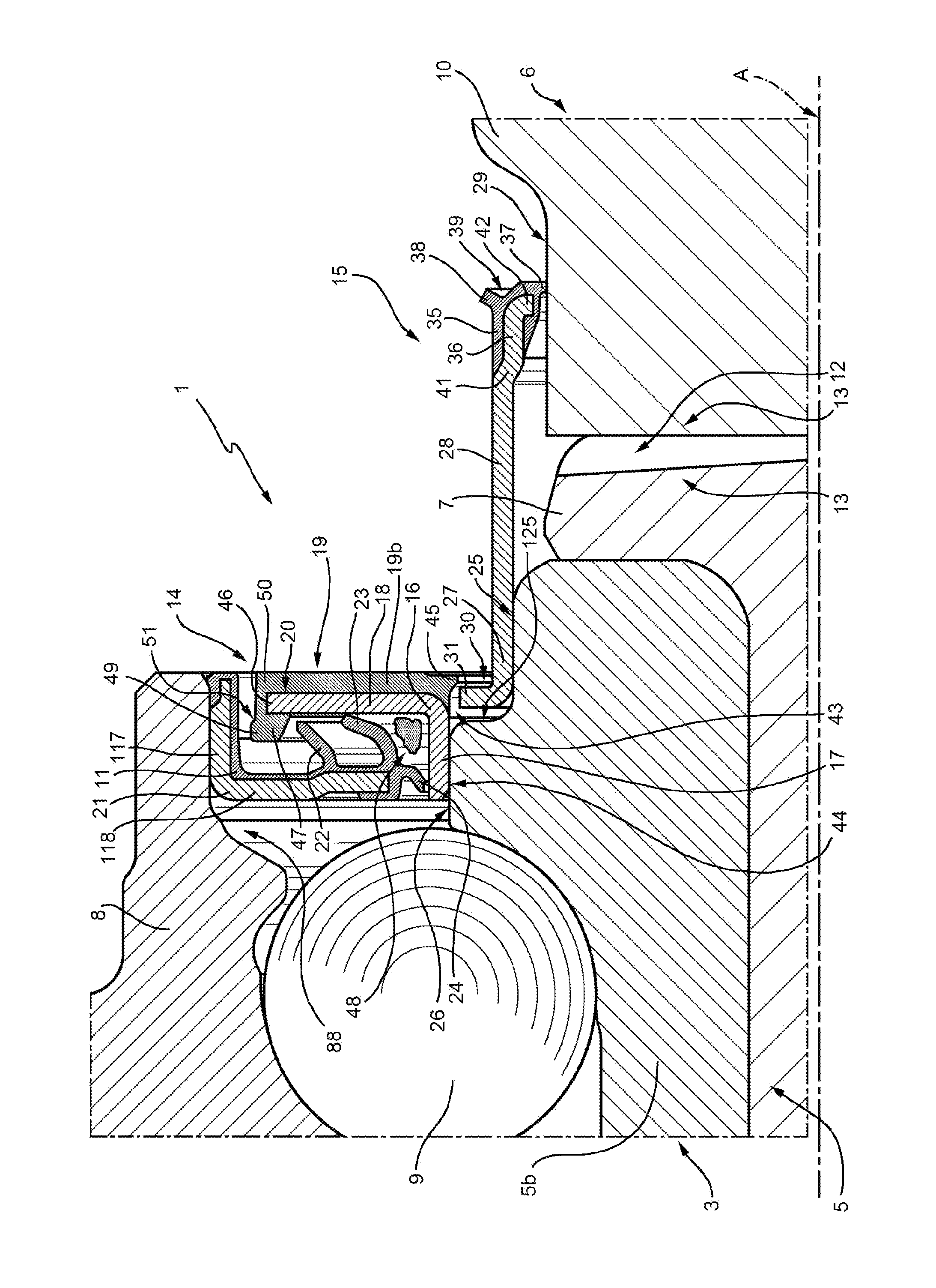
[0014]With reference to the above-mentioned figure, numeral 1 indicates a seal device as a whole for a wheel hub assembly 3, which inner ring 5 is operatively associated, for rotating integrally thereto, with a constant velocity joint 6, known and therefore illustrated only in part for simplicity. The wheel hub assembly 3 further comprises an outer ring 8 mounted coaxial and concentric with ring 5, radially externally to ring 5, and a plurality of rolling bodies 9 interposed between the rings 5 and 8. The inner ring 5 comprises a ring 5b, made as an independent element blocked axially by a rolled edge 7 and delimited externally by an outer cylindrical lateral surface 26, while the constant velocity joint 6 comprises an outer ring 10 (the only part of the constant velocity joint 6 that is shown in the drawing) provided with an outer cylindrical lateral surface 29, arranged normally substantially coaxial to ring 5, and with a toothed coupling 12 with the inner ring 5 having front toot...


PUM


Abstract

An arrangement including a first and second sealing assembly disposed between an inner ring and an outer ring of the wheel hub and straddling the wheel hub and an outer ring of a constant velocity joint, and an annular step formed on the side of the constant velocity joint on a radially outer lateral surface of the inner ring, in a position adjacent to a sleeve portion of a first shield of the first sealing assembly from a flange portion radially extends so as to protrude towards the outer ring, the flange portion being provided towards the constant velocity joint with a signal generating element (19) consisting of an annular insert; an end of a tubular core of the second sealing assembly is fitted angularly onto the step and is radially externally provided with an L-shaped edge arranged within the step and radially under the annular insert.

Description

CROSS-REFERENCE TO RELATED APPLICATIONS[0001]This application claims priority to Italian Application TO2013A000506 file Jun. 19, 2013, the contents of which are herein fully incorporated by reference.TECHNICAL FIELD OF THE INVENTION[0002]The present invention relates to a low friction seal device for wheel hub assemblies connected to constant velocity joints and to the respective arrangement thereof.BACKGROUND OF THE INVENTION[0003]Wheel hub assemblies, on the one hand, support a vehicle wheel and, if the wheel is a drive wheel, are angularly connected to a related constant velocity joint for the transmission of the driving torque from the axle shaft to the wheel itself. Wheel hub assemblies have an axis of rotation and comprise an inner ring and an outer ring which are coaxial to each other and to the axis of rotation, and are rotatable with respect to each other due to the interposition therebetween of two crowns of rolling bodies.KNOWN ART[0004]The transmission of driving torque ...

Claims


Application Information

Patent Timeline
IPC IPC(8): F16J15/32B60B27/00
CPCB60B27/0073F16J15/3232F16C33/768F16C33/7883F16C33/80F16C41/007F16C19/186F16C33/583F16C2326/02F16D2300/08B60B27/0005B60B27/0068Y02T10/86
Inventor DUCH, DANIELEMORELLO, FAUSTOSERAFINI, ANDREA
Owner AB SKF
Why Eureka
Try Eureka