
Amplitude tapered switched beam antenna systems

Inactive Publication Date: 2014-12-25
ALCATEL LUCENT SHANGHAI BELL CO LTD
View PDF9 Cites 8 Cited by
  • Summary
  • Abstract
  • Description
  • Claims
  • Application Information

AI Technical Summary

Benefits of technology

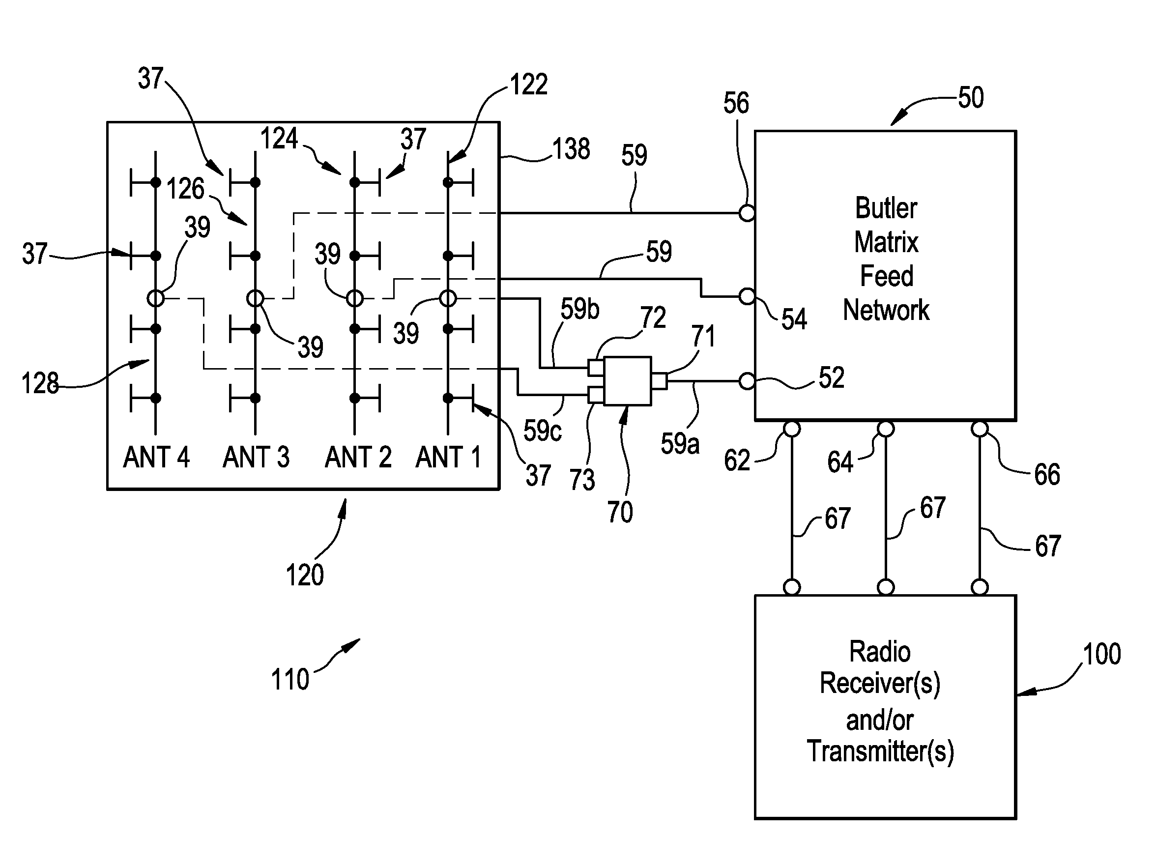
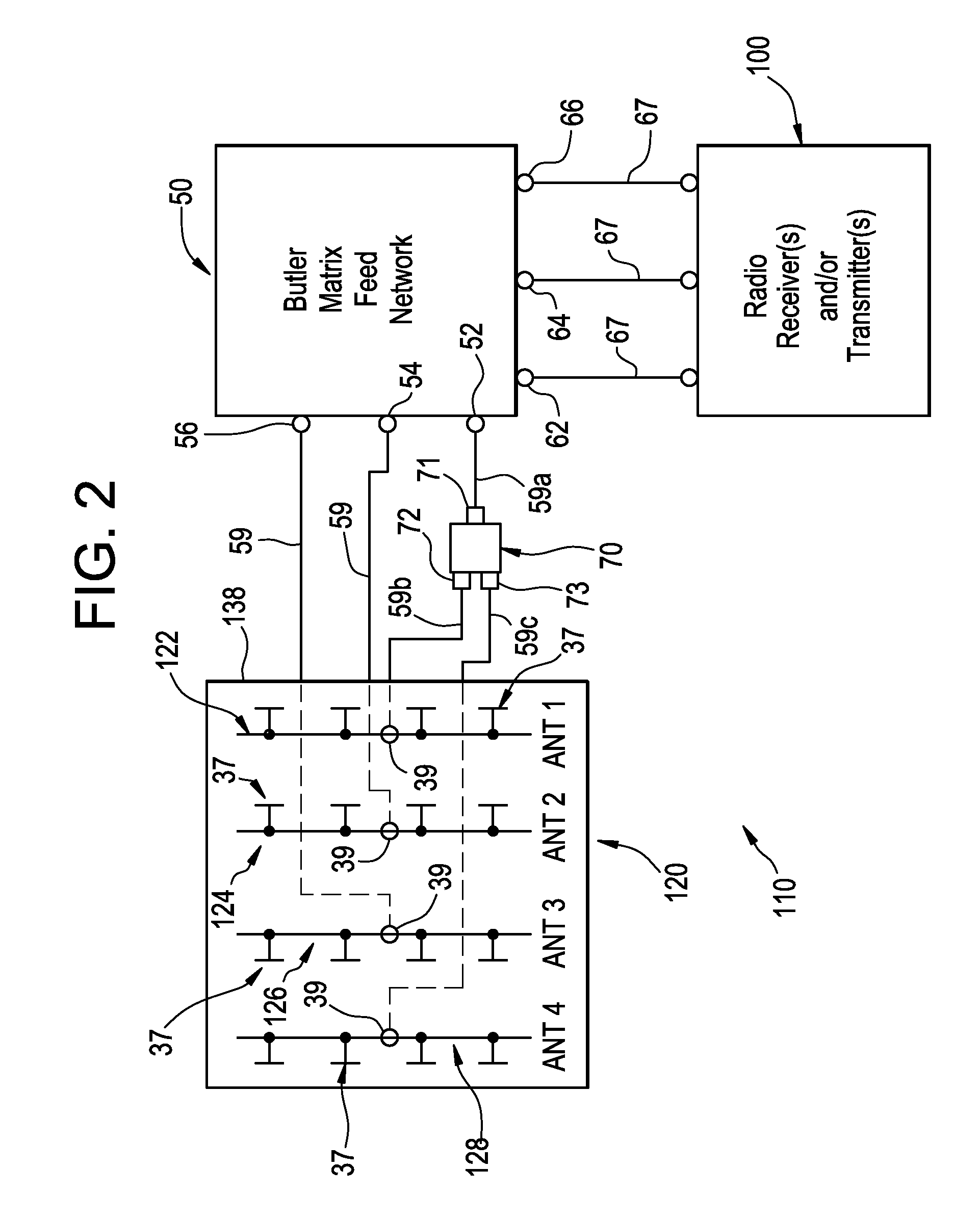
This patent is about a new type of antenna system that can create multiple beams of light by using multiple co-linear arrays of smaller antennas that work together. These arrays are connected by a phased array feed network, which splits the signal power between them. This design reduces interference and improves both side lobe suppression and antenna gain, resulting in a more efficient and effective antenna system.

Problems solved by technology

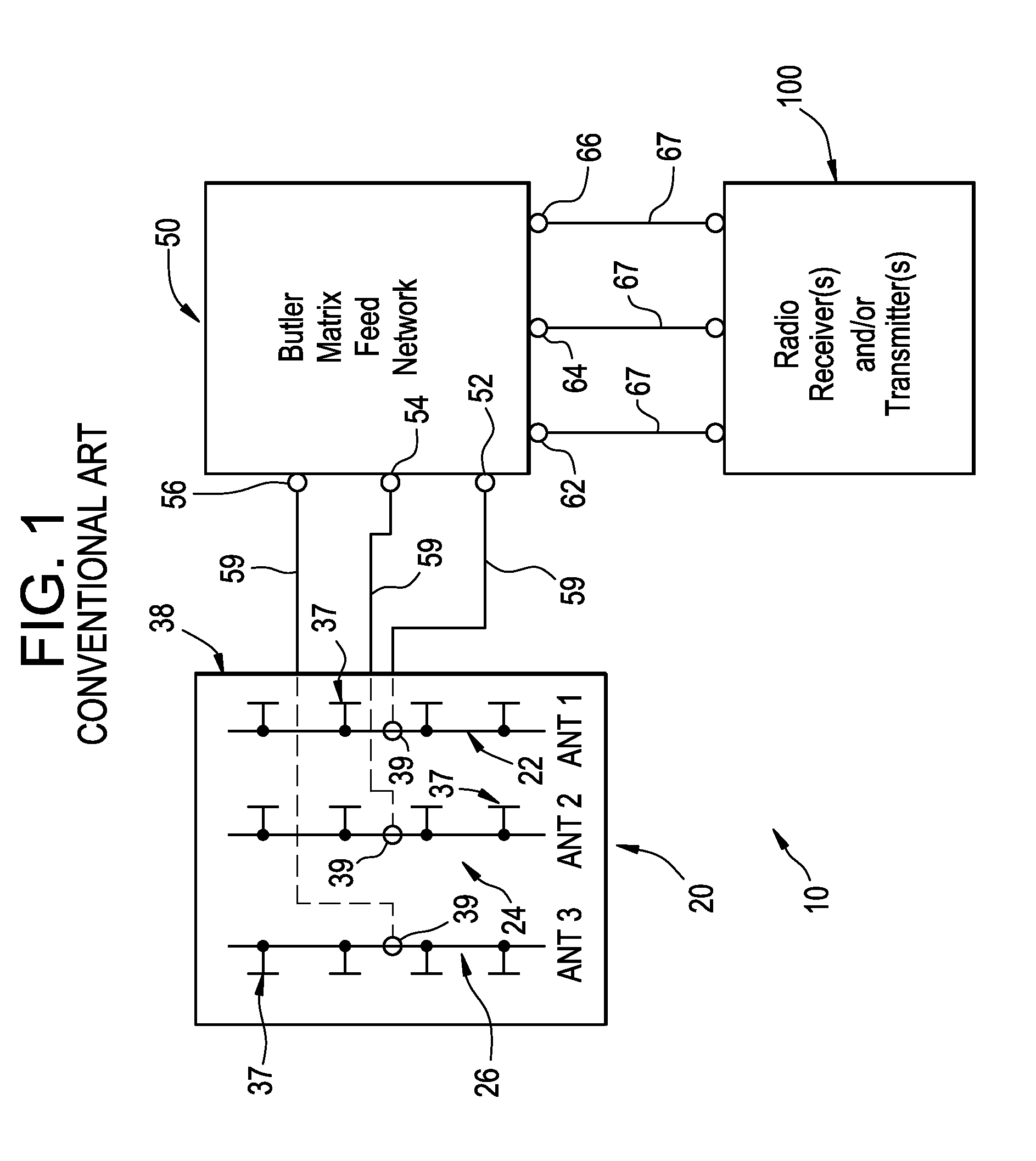
A shortcoming of systems like system 20 is that equal power division among the arrays of radiating elements results in high side lobe levels, which wastes energy and may cause interference with other equipment.
Moreover, the resulting binomial amplitude taper is highly inefficient and provides a wider beamwidth than is typical, which reduces the gain of the antenna.
However, aperture tapering is inefficient because switched beam arrays operate best when each adjacent array of dipoles has the same number of dipoles.
When the number of dipoles differs between adjacent arrays, the beam patterns of each array do not add up in phase, side lobe levels are higher than desired and the gain of the antenna is compromised.

Method used


Image

  • Amplitude tapered switched beam antenna systems
  • Amplitude tapered switched beam antenna systems
  • Amplitude tapered switched beam antenna systems

Examples


Embodiment Construction

[0023]The following description discloses various embodiments of switched beam antenna systems including Butler Matrix feed networks and multiple-array antennas configured to create multiple antenna beams. The systems are configured to provide an excellent balance between side lobe suppression and overall gain of the antennas through amplitude tapering among arrays of electromagnetic radiating elements in the antennas. The systems disclosed herein achieve these benefits without affecting the periodicity of the antenna outputs / inputs of the Butler Matrix feed network.

[0024]In the following description, reference is made to specific embodiments, components and features. Reference numbers and characters repeated between the various embodiments indicate similar components and features. It should be understood that the use of the word “includes” in the following description is meant to be non-limiting. When the word “includes” is used to describe the inclusion of a component or feature, ...


PUM


Abstract

Switched beam antenna systems are disclosed. The disclosed antenna systems include an antenna having multiple, co-linear arrays of electromagnetic radiating elements and a Butler Matrix feed network that feeds the antenna. Each of the arrays of electromagnetic radiating elements includes an identical number of radiating elements. At least one antenna port of the Butler Matrix feed network is connected to a power divider / combiner to split the signal strength at the at least one antenna port such that signal power is distributed unequally among the arrays of electromagnetic radiating elements. Power is distributed among the arrays in a manner that provides an improved balance of side lobe suppression and overall antenna gain.

Description

BACKGROUND[0001]Switched beam antenna systems employing Butler Matrix feed networks are well known. In a basic type of conventional switched beam antenna system, a Butler Matrix feed network has N antenna ports, where ‘N’ is a number greater than one, feeding (when transmitting signals) or fed by (when receiving signals) N arrays or columns of radiating elements. The Butler Matrix feed network divides signal power equally amongst the arrays of radiating elements and provides different phase progressions depending on which receiver / transmitter port of the Butler Matrix feed network is used. By varying the phase progressions, the main beam of the antenna can be ‘switched’ from one point to another.[0002]FIG. 1 shows an exemplary, basic conventional stitched beam antenna system 10 including a switched beam antenna 20, a Butler Matrix feed network 50 and one or more radio receivers and / or radio transmitters 100. The antenna 20 includes three co-linear arrays (or “columns”) 22, 24, 26 of...

Claims


Application Information

Patent Timeline
IPC IPC(8): H01Q21/00H01Q9/16
CPCH01Q9/16H01Q21/0006H01Q3/40H01Q21/22
Inventor POWELL, CHARLES M.KATIPALLY, RAJA REDDY
Owner ALCATEL LUCENT SHANGHAI BELL CO LTD
Learn More