
Manufacturing method for liquid crystal display

Inactive Publication Date: 2014-12-25
NITTO DENKO CORP
View PDF4 Cites 11 Cited by
  • Summary
  • Abstract
  • Description
  • Claims
  • Application Information

AI Technical Summary

Benefits of technology

The present invention relates to improving liquid crystal display panels by using an optical film with a special polarizing film. This film helps to control the direction of light in the display, resulting in better image quality and manufacturing efficiency. Overall, this invention allows for the production of high-quality liquid crystal display panels.

Problems solved by technology

Consequently, there arises a problem in that a manufacturing apparatus is increased in complexity, size, and cost.
However, when the polarizing film having an absorption axis in its width direction is used, there arises a problem in that display characteristics of a liquid crystal display panel to be obtained are insufficient.

Method used


Image

  • Manufacturing method for liquid crystal display
  • Manufacturing method for liquid crystal display
  • Manufacturing method for liquid crystal display

Examples


Embodiment Construction

[0043]Hereinafter, preferred embodiments of the present invention are described with reference to the drawings. However, the present invention is not limited to these specific embodiments.

[0044]I. Manufacturing Method for Liquid Crystal Display Panel

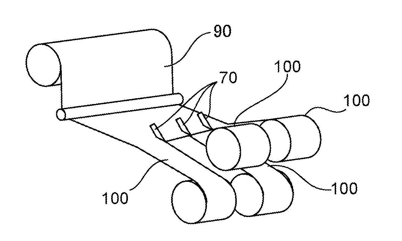
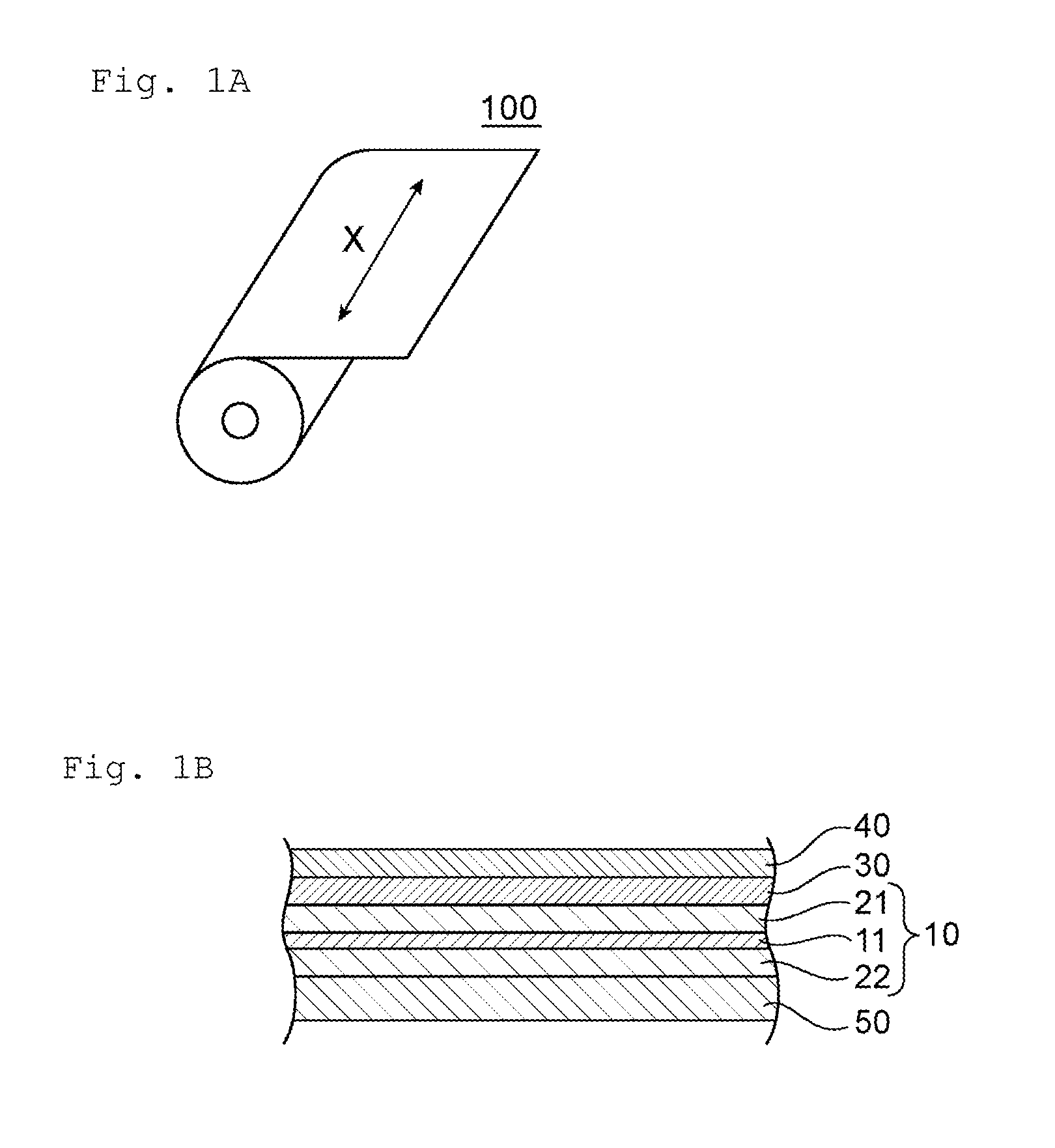
[0045]One embodiment of the present invention relates to a manufacturing method for a liquid crystal display panel. The liquid crystal display panel includes a liquid crystal cell and optical films arranged on both sides of the liquid crystal cell. The optical films each include a polarizing plate including a polarizing film. In the liquid crystal display panel, the polarizing films on both sides of the liquid crystal cell typically have absorption axes substantially perpendicular to each other. The manufacturing method according to the one embodiment of the present invention includes the steps of: cutting, while feeding a first optical film from an optical film roll, the optical film roll being obtained by slitting the first optical fil...


PUM

PropertyMeasurementUnit
Lengthaaaaaaaaaa
Widthaaaaaaaaaa
Sensitivityaaaaaaaaaa

Abstract

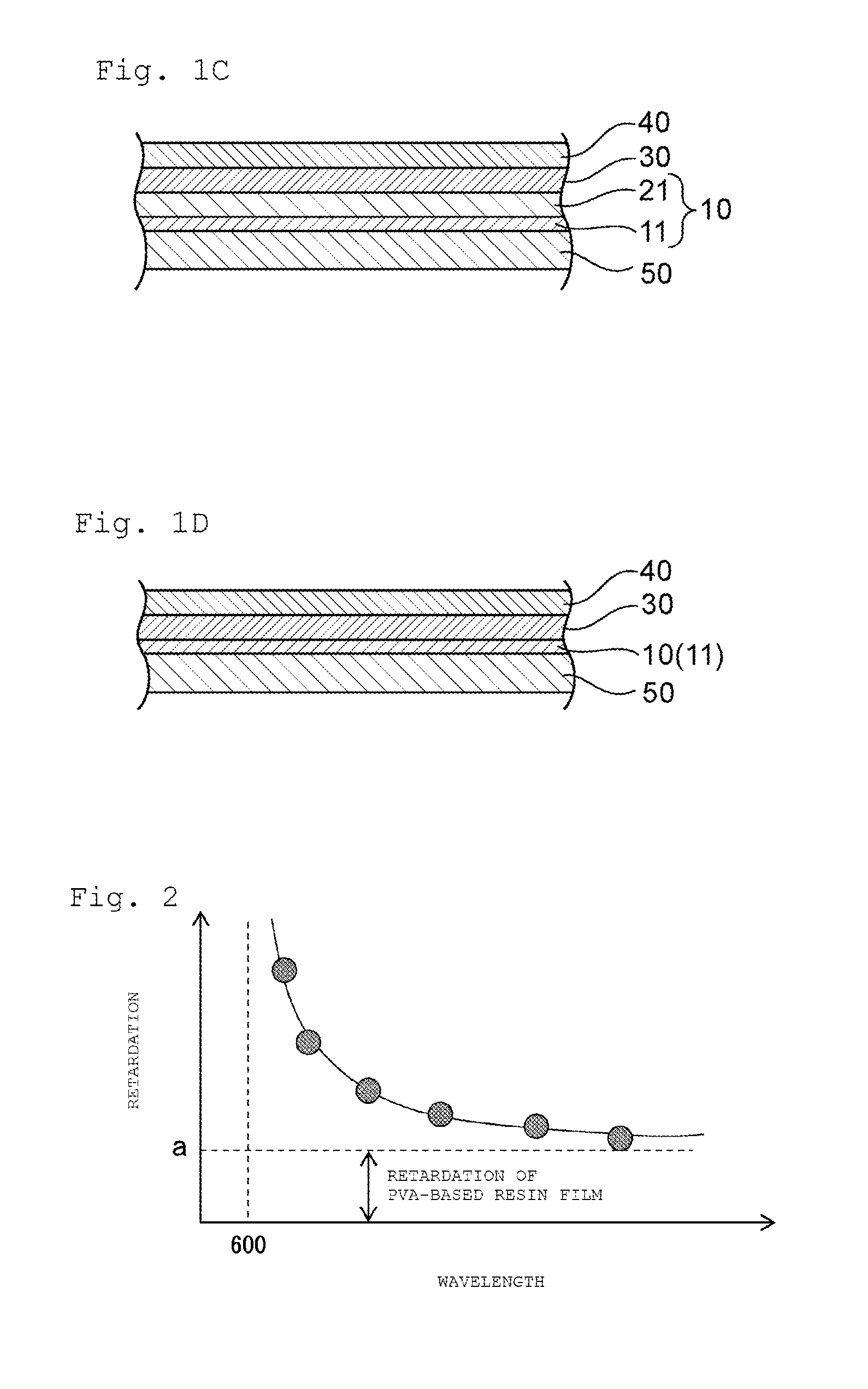
A manufacturing method for a liquid crystal display panel includes the steps of slitting a first optical film which includes a polarizing film having an absorption axis in its width direction, the polarizing film including a polyvinyl alcohol-based resin film containing a dichromatic substance and has an Nz coefficient of 1.10 or more, and rolling the slit first optical film in its width direction; slitting a second optical film, which includes a polarizing film having an absorption axis in its longitudinal direction, and rolling the slit second optical film in its width direction; bonding the cut first optical film onto one surface of the liquid crystal cell; and bonding the cut second optical film onto another surface of the liquid crystal cell.

Description

TECHNICAL FIELD[0001]The present invention relates to a manufacturing method for a liquid crystal display panel.BACKGROUND ART[0002]There are many proposals concerning a method involving, in a manufacturing line for a liquid crystal display panel, cutting a roll-shaped optical film while feeding the optical film to attach the optical film to a liquid crystal cell (so-called roll-to-panel; RTP) (for example, Patent Literature 1). For example, in Patent Literature 1, there is a disclosure of a method involving: while feeding a long optical film from an optical film roll, cutting the optical film to a length corresponding to a long side of a liquid crystal cell to attach the optical film to one surface of the liquid crystal cell, the optical film roll being obtained by winding a long optical film that includes a polarizing film having an absorption axis in its longitudinal direction and has been subjected to cutting (slitting process) to a width corresponding to a short side of the liq...

Claims


Application Information

Patent Timeline
IPC IPC(8): G02F1/1335G02F1/1333G02F1/13
CPCG02F1/133528G02F1/1333G02F1/1303B29C55/023B29K2029/04B32B2038/045B32B2457/202G02B5/3033G02B5/305G02F1/133536
Inventor HADA, KAZUYAARAKI, TATSUYAKONDO, SEIJIHIRATA, SATOSHI
Owner NITTO DENKO CORP
Learn More