Manufacturing method of substrate having function layer between partition walls, and manufacturing method of image display apparatus using the substrate

Inactive Publication Date: 2011-09-08
CANON KK
View PDF3 Cites 0 Cited by
  • Summary
  • Abstract
  • Description
  • Claims
  • Application Information

AI Technical Summary

Benefits of technology

[0011]According to the present invention, the function layers are formed after the water solvable polymer layer is formed on the top of the partition walls, and the unnecessary substance adhering to the top of the partition walls is removed together with the water solvable polymer layer by water rinsing. Thus, the unnecessary substance adhering to the top of the partition walls can be removed without affecting the function layers formed between the partition walls, and adverse effects, for example, the adhesion decrease of a member, such as a wiring, formed on the top of the partition walls in a subsequent step, can be prevented. Therefore, a display substrate with high reliability, and an image display apparatus with excellent display characteristics can be easily provided with good precision.

Problems solved by technology

However, due to a change in the shape of the screen plate over time, the paste may adhere to the top of the partition wall.
When this paste adhesion occurs, the adhesiveness of a forming material, such as a metal back, laminated on the top of the partition walls to the partition walls decreases, and the peeling of the metal back and pattern failure may occur.
However, in a method for removing a substance adhering to the top of partition walls, using the tackiness of a tacky body, as in Japanese Patent Application Laid-Open No. 2004-319460, it is necessary to surely adhere the tacky body to the top of the partition walls and further surely peel the tacky body.
But, if the tackiness of the tacky body is insufficient, the removal efficiency of the substance adhering decreases.
Therefore, it cannot be said that the effect of removing the substance adhering is sufficient.

Method used


Image

  • Manufacturing method of substrate having function layer between partition walls, and manufacturing method of image display apparatus using the substrate
  • Manufacturing method of substrate having function layer between partition walls, and manufacturing method of image display apparatus using the substrate
  • Manufacturing method of substrate having function layer between partition walls, and manufacturing method of image display apparatus using the substrate

Examples


example 1

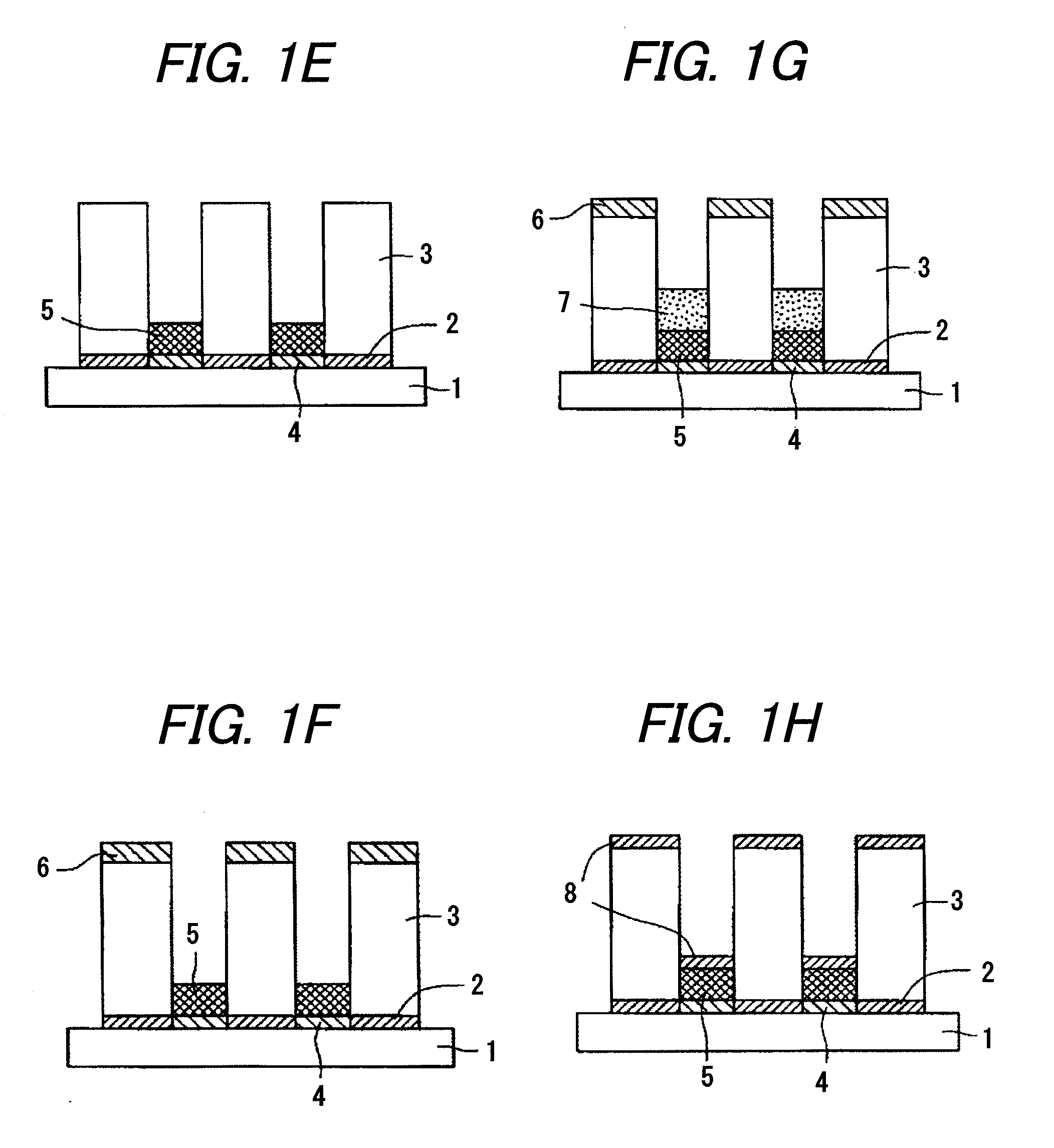
[0036]Based on the manufacturing method of a display substrate exemplified in FIGS. 1A to 1H, a display substrate is manufactured by the following steps.

[0037](Step 1: Formation of Light Shielding Layer 2)

[0038]A black paste (NP-7811M1, manufactured by NORITAKE CO., LIMITED) was printed on an entire surface of the glass substrate 1 washed. This substrate 1 was dried at 150° C., then exposed at 1000 mJ / cm2, developed, and baked at 580° C. to form the light shielding layer 2 having a thickness of 5 μm and having openings with a horizontal pitch of 210 μm, a vertical pitch of 630 μm, and an opening size of 150×200 μm.

[0039](Step 2: Formation of Partition Walls 3)

[0040]An insulating paste obtained by adding alumina having an average particle diameter of about 5 μm to borosilicate glass was deposited on the center lines between the 210 μm pitches of the pixels of the light shielding layer 2 by a slit coater. This substrate was dried at 95° C., then exposed at 300 mJ / cm2, developed, and b...


PUM


Abstract

The present invention provides a manufacturing method of a display substrate that can easily remove a substance adhering to the top of partition walls with high precision. On a substrate, partition walls for dividing a surface of the substrate into a plurality of regions are formed, and a color filter layer and a light emitting layer are formed in the regions. Then, a water solvable polymer layer is deposited at the top of the partition walls, and a planarized layer is formed on the light emitting layer. Then, the water solvable polymer layer formed on the top of the partition walls is removed by water rinsing to remove a substance adhering to the top of the partition walls.

Description

BACKGROUND OF THE INVENTION[0001]1. Field of the Invention[0002]The present invention relates to a manufacturing method of a display substrate having a function layer, such as a light emitting layer for emitting a light responsive to electron bombardment, in a plurality of regions divided by a partition wall, and a manufacturing method of an image display apparatus using the display substrate.[0003]2. Description of the Related Art[0004]A plasma display (PDP) and a field emission display (FED) known as a flat panel display have partition walls in the internal structure, and function layers are formed in a plurality of regions divided by the partition walls. For example, in the PDP, an electrode layer, an insulating layer and a phosphor layer are formed in the regions divided by the partition walls, and in the FED a pigment layer, a phosphor layer and a planarized layer are formed in the regions divided by the partition walls. When these function layers are formed, generally, a metho...

Claims


Application Information

Patent Timeline
IPC IPC(8): B05D5/06
CPCB05D5/06H01J31/127H01J9/242H01J9/241H01J9/148H01J9/20
Inventor ISHIOKA, YOSHITAKA
Owner CANON KK
Why Eureka
Try Eureka