
Liquid-crystal display element

Active Publication Date: 2017-07-27
DAINIPPON INK & CHEM INC
View PDF5 Cites 3 Cited by
  • Summary
  • Abstract
  • Description
  • Claims
  • Application Information

AI Technical Summary

Benefits of technology

The FFS mode liquid crystal display element described in this patent is fast-responsive and produces very few display defects. It also reduces alignment unevenness and has excellent display quality, making it useful for applications like TVs and monitors.

Problems solved by technology

This is because the FFS mode does not produce a perfect parallel electric field unlike the IPS mode, and in the case of using the p-type material, the liquid crystal molecules close to the pixel electrode tilt along the fringe electric field of the major axis of the liquid crystal molecules, thereby deteriorating the transmittance.
Therefore, nothing is known about problems such as burn-in or drip mark for which it is difficult to predict the effects with the related art.
Accordingly, even if the liquid crystal composition used for VA is simply used for this purpose, it is difficult to form a high-performance liquid crystal display element as required today, and therefore, there is a demand to provide an n-type liquid crystal composition optimized for FFS mode.

Method used


Image

  • Liquid-crystal display element
  • Liquid-crystal display element
  • Liquid-crystal display element

Examples


example 1 (

(Example 1 (Liquid Crystal Composition 1))

[0335]The liquid crystal composition (liquid crystal composition 1) having the compositional ratio described below was prepared, and the physical properties thereof were measured. The results are shown in the following Table.

[0336]Using the liquid crystal composition 1, an FFS mode liquid crystal display element was produced having a cell thickness of 3.0 μm, which is common for TVs, and having electrode layers on the first substrate and the second substrate. The injection of the liquid crystal composition was carried out by a dripping method, and evaluations of burn-in, drip marks, process adaptability, and solubility at low temperature were carried out.

[0337]The references on the left side of the content are abbreviations of the compounds described above.

[Chem. 72]3CyCyV31%3CyCyV111%3CyPh5O213%5CyPh5O2 6%3CyCyPh5O211%2CyCyPh5O2 5%3CyPhPh5O210%3PhPh5Ph213%

example 1

[0338]

TABLE 1TNI / °C.75.6Δn0.109no1.483Δε−3.07ε⊥6.62η / mPa · s15.2γ1 / mPa · s98γ1 / Δn2 × 10−38.2γ1 / Δn2 / |Δε|2.69Initial voltage holding99.6ratio %Voltage holding ratio %99 .0after 1 hour at 150° C.Burn in evaluationADrip mark evaluationAProcess adaptabilityAevaluationSolubility at lowAtemperature evaluation

[0339]The liquid crystal composition 1 has a TNI of 75.6° C., which is practical in terms of a liquid crystal composition for a TV, has a large Δ∈ absolute value, a low η, and an optimum Δn. An FFS mode liquid crystal display element was produced using the liquid crystal composition 1 and evaluated for burn-in, drip marks, process adaptability, and solubility at low temperature using the method described above, and the evaluation results were extremely excellent.

[0340]In addition, a liquid crystal display element prepared under a polarizing microscope was installed and, when a voltage was applied in this state and observation was carried out, the driving was confirmed in a state where ...

example 2 (

(Example 2 (Liquid Crystal Composition 2))

[0341]A liquid crystal composition (liquid crystal composition 2) having the following composition having the following composition designed to have an equivalent TNI, an equivalent Δn value, and an equivalent Δ∈ value to those of liquid crystal composition 1 was prepared, and the physical property values thereof were measured. The results are shown in the following table.

[0342]Using the liquid crystal composition 2, an FFS mode liquid crystal display element was produced in the same manner as in Example 1, and the results of evaluations of burn-in, drip mark, process adaptability, and solubility at low temperature are shown in the same table.

TABLE 23CyCyV32%3CyCyV112%3CyCyPh1 4%3CyPh5O2 7%3PnPh5O210%3CyCyPh5O210%4CyCyPh5O2 2%2CyPhPh5O2 5%3CyPhPh5O2 8%3PhPh5Ph2 5%4PhPh5Ph2 5%TNI / ° C.76.6Δn  0.110no  1.485Δε −3.03ε⊥ 6.36η / mPa · s13.6γ1 / mPa · s90  γ1 / Δn2 × 10−3 7.4γ1 / Δn2 / |Δε| 2.45Initial voltage holding99.5ratio %Voltage holding ratio %99.0aft...


PUM


Abstract

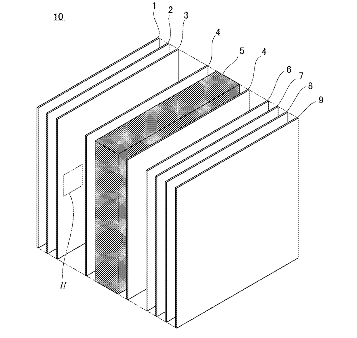
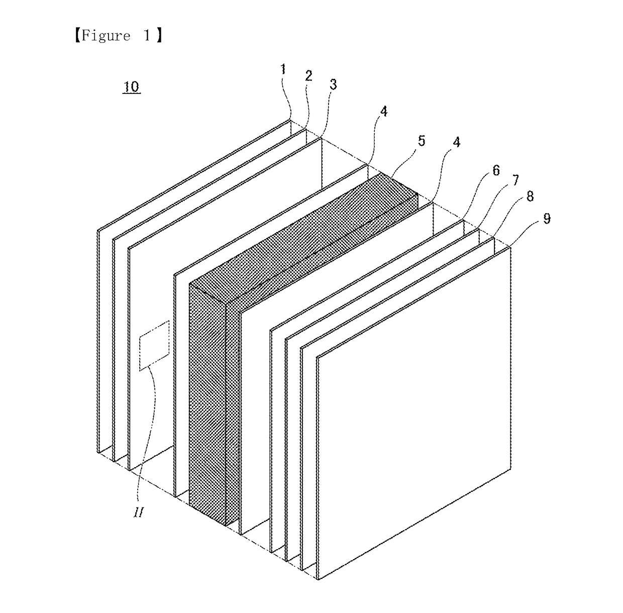
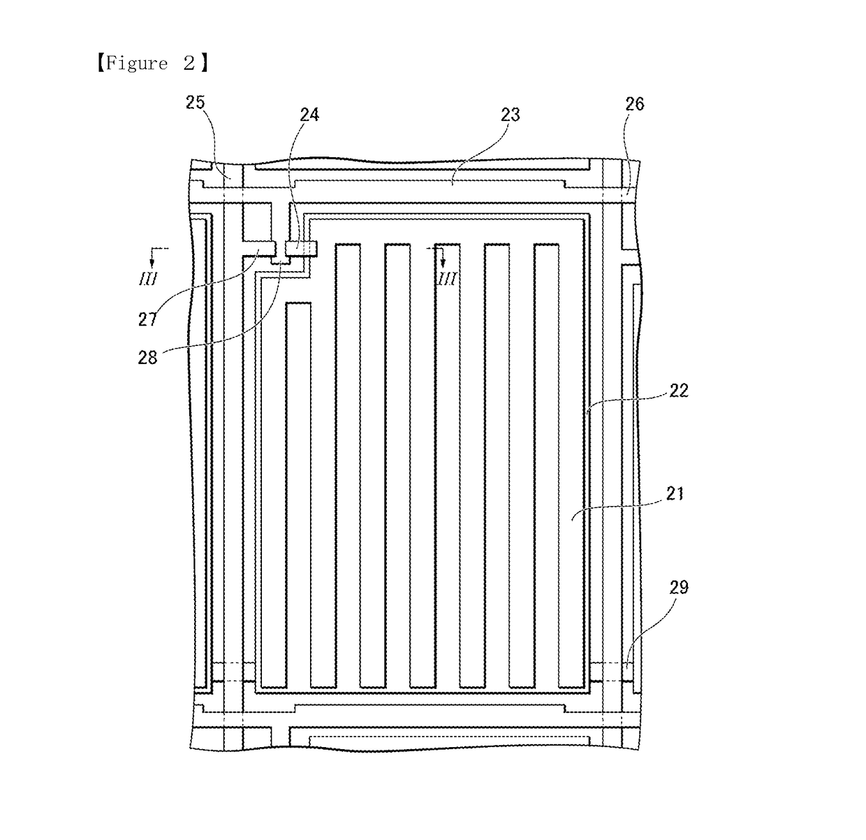
There is provided a liquid crystal display element. The liquid crystal layer contains a liquid crystal composition between the first substrate and the second substrate. The first common electrode contains a transparent conductive material on the first substrate. The second common electrode contains a transparent conductive material on the second substrate. The pixel electrode contains a transparent conductive material. Distances R between the pixel electrode and the common electrode is smaller than distance G between the first substrate and the second substrate. The common electrode is disposed closer to the first substrate than the pixel electrode over nearly the entire surface of the first substrate. The liquid crystal composition has negative dielectric anisotropy and contains one or two or more compounds selected from the group of compounds represented by General Formula (i), General Formula (ii), and General Formula (iii).

Description

TECHNICAL FIELD[0001]The present invention relates to an FFS mode liquid crystal display device using a nematic liquid crystal composition having negative dielectric anisotropy, which has high transmittance and a high opening ratio.BACKGROUND ART[0002]From the fact that display quality is excellent, active matrix type liquid crystal display elements have been put on the market for portable terminals, liquid crystal televisions, projectors, computers and the like. In the active matrix type elements, thin film transistors (TFT), metal-insulator-metals (MIM), or the like are used for each pixel, and it is important that the liquid crystal compound or the liquid crystal composition used in this type has a high voltage holding ratio. In addition, a liquid crystal display element which includes a Vertical Alignment (VA) mode, an In-Plane Switching (IPS) mode, and an Optically Compensated Bend, Optically Compensated Birefringence (OCB) mode in combination is proposed in order to obtain wid...

Claims


Application Information

Patent Timeline
IPC IPC(8): C09K19/30G02F1/1343G02F1/1362G02F1/1368G02F1/1337
CPCC09K19/3066G02F2001/134372G02F1/1368G02F1/1337G02F1/136286G02F1/13439G02F1/134309C09K2019/3004C09K2019/3009C09K2019/301C09K2019/3016G02F2001/133738G02F2201/121G02F2201/123C09K19/3003C09K19/322C09K19/44C09K2019/123C09K2019/3425G02F1/137G02F1/134372G02F1/13712C09K19/12C09K19/14C09K19/16C09K19/18C09K19/20C09K19/30C09K19/32C09K19/34C09K19/42G02F1/1343G02F1/133738
Inventor MARUYAMA, KAZUNORIIWASHITA, YOSHINORIOGAWA, SHINJI
Owner DAINIPPON INK & CHEM INC
Learn More