Curved display panel manufacturing method

a technology of display panels and manufacturing methods, applied in the direction of instruments, other domestic objects, chemistry apparatuses and processes, etc., can solve the problems of high manufacturing cost, difficult manufacturing process, and inability to be used

Inactive Publication Date: 2015-01-01
TOVIS
View PDF11 Cites 90 Cited by
  • Summary
  • Abstract
  • Description
  • Claims
  • Application Information

AI Technical Summary

Benefits of technology

[0015]The removal of the outer surface of the liquid crystal panel to reduce the lower substrate and the upper substrate from which the polarizing plates are separated to a designated thickness may include masking parts of the upper substrate or the lower substrate where protrusions separating the transparent substrates from the lower substrate or the upper substrate will be formed with masking members preventing removal of the outer surface of the liquid crystal panel so as to form the protrusions.

Problems solved by technology

Therefore, if a curved display is required, the general flat liquid crystal panel may not be used.
However, the above conventional flexible liquid crystal panel has a difficult manufacturing process and high manufacturing costs.

Method used


Image

  • Curved display panel manufacturing method
  • Curved display panel manufacturing method
  • Curved display panel manufacturing method

Examples


Embodiment Construction

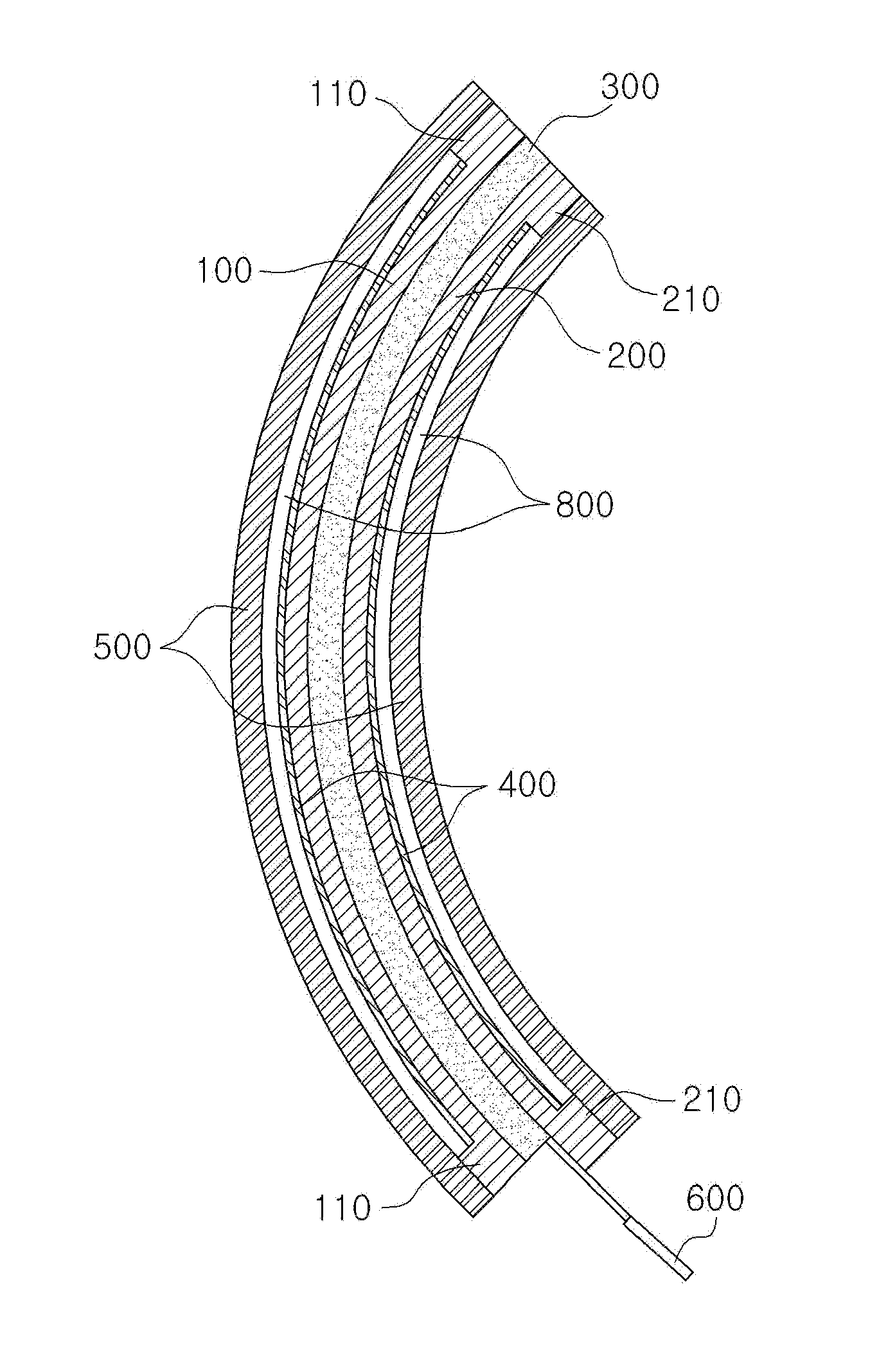
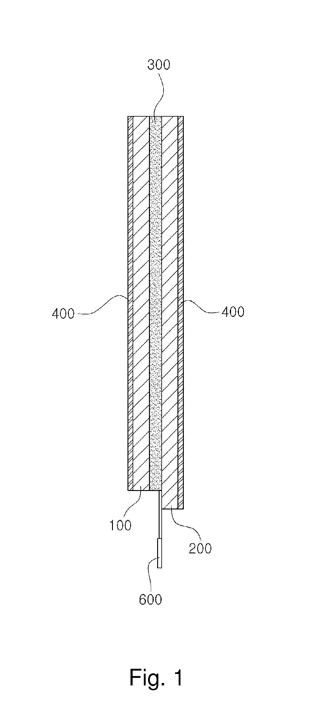
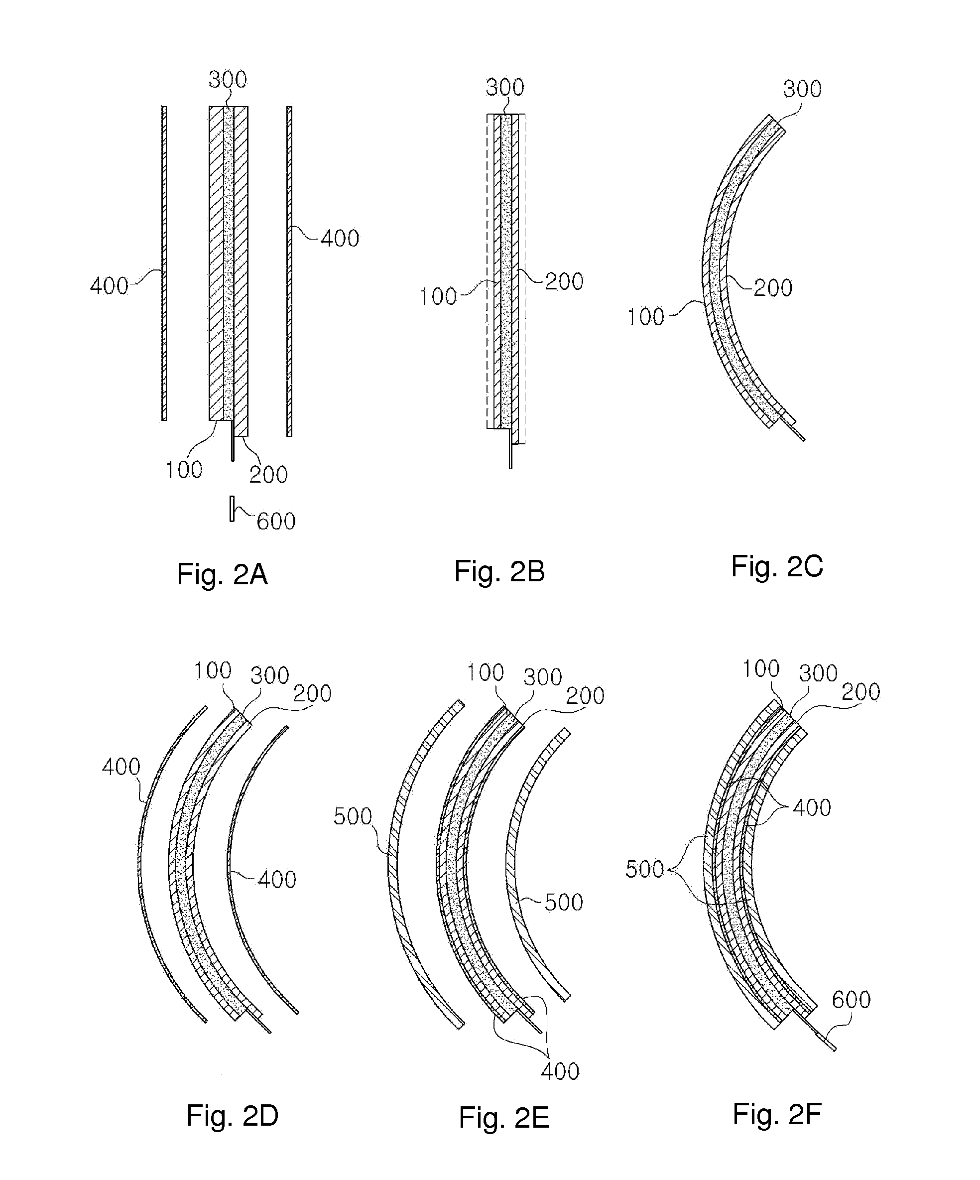
[0029]Hereinafter, embodiments of the present invention will be described in more detail with reference to the accompanying drawings.

[0030]In the drawings, the thickness of each of several layers and regions is exaggerated for convenience of description and clarity. Wherever possible, the same reference numbers will be used throughout the drawings to refer to the same or like parts. It will be understood that when an element is referred to as being “on” or “under” another element, it can be directly on / under the element, and one or more intervening elements may also be present. However, when an element is referred to as being directly “on” or “under” another element, one or more intervening elements are not present.

[0031]Further, in the specification, the terms “two substrates”, “lower substrate” and “upper substrate” include the concept of one or both of a lower substrate and an upper substrate.

[0032]A display panel manufacturing method in accordance with one embodiment of the pres...


PUM

PropertyMeasurementUnit
temperatureaaaaaaaaaa
thicknessaaaaaaaaaa
thicknessaaaaaaaaaa

Abstract

A curved display panel manufacturing method is provided. The curved display panel manufacturing method in which a display panel in a desired curved shape is manufactured using a prefabricated flat liquid crystal panel including a lower substrate and an upper substrate formed of glass and opposite each other, each of the lower substrate and an upper substrate being provided with a polarizing plate, and a liquid crystal layer formed between the lower substrate and the upper substrate, includes separating the polarizing plates from the lower substrate and the upper substrate, removing the outer surface of the liquid crystal panel to reduce the lower substrate and the upper substrate from which the polarizing plates are separated to a designated thickness, and bending the liquid crystal panel having the removed outer surface in a desired curved shape.

Description

REFERENCE TO RELATED APPLICATION[0001]This application is continuation-in-part application of application Ser. No. 13 / 394,585 filed on Mar. 7, 2012, the disclosure of which is incorporated by reference in its entirety.BACKGROUND OF THE INVENTION[0002]1. Field of the Invention[0003]The present invention relates to a display panel manufacturing method for manufacturing a display panel in a curved shape.[0004]2. Description of the Related Art[0005]As display technology advances, various kinds of display devices are being developed and used. From among these display devices, there is a liquid crystal display device to display an image using liquid crystals.[0006]A liquid crystal panel of a general liquid crystal display (LCD) includes two substrates and a liquid crystal layer having dielectric anisotropy interposed between the two substrates. The liquid crystal panel applies an electric field to the liquid crystal layer and adjusts an intensity of the electric field to adjust transmitta...

Claims


Application Information

Patent Timeline
Patent Type & Authority Applications(United States)
IPC IPC(8): B32B38/10B32B37/12B32B43/00B32B37/18B32B37/14B32B38/18
CPCB32B38/1866B32B37/144B32B38/10B32B43/006B32B2457/202B32B37/18B32B2307/40B32B2307/42B32B37/1284B32B2037/1253B32B2310/0831G02F1/1333Y10T156/103B32B17/10B29C45/1671B29K2709/08B29K2995/0026B29K2995/0034B29L2031/3475B32B37/12B32B2307/412G02F1/133528G02F1/133302Y10T156/1028
Inventor KIM, YONG BEOMPARK, WOON YONG
Owner TOVIS
Why Eureka
Try Eureka