Electric cartridge type heater and method for manufacturing same

a heater and electric cartridge technology, applied in the direction of heaters, heater elements, heating element shapes, etc., can solve the problems of reducing the speed with which the coiling machine can be operated, being susceptible to problems, expensive, etc., and unable to direct apply this principl

Active Publication Date: 2015-01-01
TUERK & HILLINGER
View PDF21 Cites 13 Cited by
  • Summary
  • Abstract
  • Description
  • Claims
  • Application Information

AI Technical Summary

Benefits of technology

[0015]An object of the present invention is therefore to provide an improved, especially more reliabl

Problems solved by technology

The direct application of this principle is not possible in case of electric cartridge type heaters in which the electric contacting is to take place from one side, only because it presupposes that the heat conductor can be mechanically stressed during the filling of the electric cartridge type heater with the insulating material.
However, it is seen in practice that the arrangement of the heat conductor on a coil body or such a carrier structure entails a great effort in terms of manufacturing technology and is susceptible to problems and is expensive.
However, this leads not only to problems if a reduced space is required for construction, but also to stronger forces to be applied when feeding and removing the coil body into and from the coiling machine and when inserting and tightening the heat conductor in the hole of the coil body, which may even lead to breakage of the coil

Method used


Image

  • Electric cartridge type heater and method for manufacturing same
  • Electric cartridge type heater and method for manufacturing same
  • Electric cartridge type heater and method for manufacturing same

Examples


Embodiment Construction

[0071]Referring to the drawings in particular, identical components of identical exemplary embodiments are designated by identical reference numbers in all figures. The features illustrated on the basis of individual embodiments can be applied to all other embodiments unless they are in direct conflict with one another.

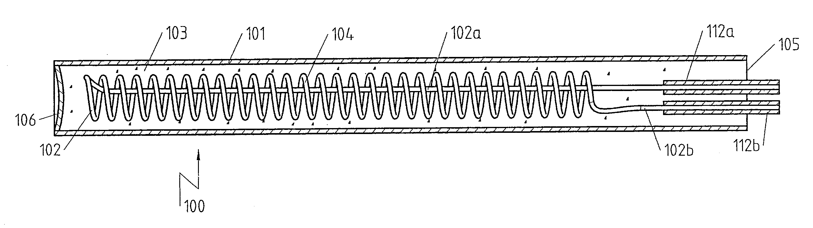
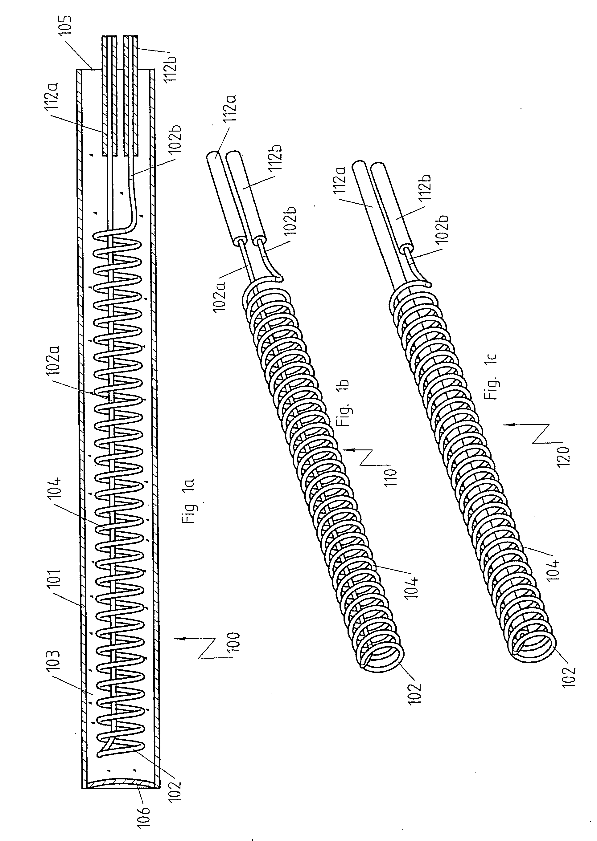
[0072]FIG. 1a shows an electric cartridge type heater 100 with a first tubular metallic jacket 101 and with a self-supporting electric heat conductor 102 arranged in the interior tubular space of the first tubular metallic jacket 101 with two ends 102a, 102b for electrically contacting the self-supporting electric heat conductor 102. The self-supporting electric heat conductor 102 is electrically insulated from the first tubular metallic jacket 101 by an electrically insulating material 103, e.g., magnesium oxide, arranged in the interior space of the first tubular metallic jacket 101. The two ends 102a, 102b of the at least one self-supporting electric heat conductor...


PUM

PropertyMeasurementUnit
Diameteraaaaaaaaaa
Electrical conductoraaaaaaaaaa
Heataaaaaaaaaa

Abstract

An electric cartridge type heater (100, 200, 300, 400, 500, 600, 700, 800, 900, 1000) has at least one the tubular metallic jacket (101, 201, 301, 401, 501, 601, 701, 801, 901, 1001), at least one electric heat conductor (102, 202, 302, 402, 502, 602, 702, 802, 902, 1002) arranged in the interior space of the tubular metallic jacket with two ends for electrically contacting the electric heat conductor, wherein the at least one electric heat conductor is electrically isolated from the tubular metallic jacket by an electrically insulating material (103, 203, 303, 403, 503, 603, 703, 903) arranged in the interior space of the tubular metallic jacket (101, 201, 301, 401, 501, 601, 701, 801, 901, 1001). The electric heat conductor is self-supporting. A method is also provided for manufacturing such an electric cartridge type heater.

Description

CROSS REFERENCE TO RELATED APPLICATIONS[0001]This application claims the benefit of priority under 35 U.S.C. §119 of German Patent Application DE 10 2013 212 205.5 filed Jun. 26, 2013, the entire contents of which are incorporated herein by reference.FIELD OF THE INVENTION[0002]The present invention pertains to an electric cartridge type heater having least one first tubular metallic jacket, at least one electric heat conductor arranged in the interior of the first tubular metallic jacket, with two ends for electrically contacting the electric heat conductor, wherein the at least one electric heat conductor is electrically insulated from the first tubular metallic jacket by an electrically insulating material arranged in the interior of the first tubular metallic jacket, and the present invention further pertains to a method for manufacturing an electric cartridge type heater.BACKGROUND OF THE INVENTION[0003]Electric cartridge type heaters have been known for many years. They usuall...

Claims


Application Information

Patent Timeline
IPC IPC(8): H05B3/06H01C17/28H01C17/02H01C17/04H05B3/44
CPCH05B3/44H05B3/06H01C17/28H01C17/04H01C17/02Y10T29/49096Y10T29/49083H01C3/14H01C1/02
Inventor SCHLIPF, ANDREAS
Owner TUERK & HILLINGER
Why Eureka
Try Eureka