With the rise of
hydraulic fracturing over the past decade, there is a steep
climb in proppant demand Global supplies are currently tight.
However, it may break down or crush more readily under stress due to the relatively fewer grain-to-grain contact points to bear the stress often incurred in deep oil- and gas-bearing formations.
Typically, it has been difficult to effectively store the proppant at the fracturing sites.
Additionally, it has been found to be rather difficult to effectively transport the proppant to the desired location.
Under such circumstances, the proppant is often exposed to
adverse weather conditions.
This will effectively degrade the quality of the proppant during its storage.
With the development and acceptance of the
well stimulation methodology known as “hydraulic fracturing”, a unique logistics challenge has been created in delivering the massive quantities of proppant from domestic sand mines to the
wellhead.
This logistics challenge affects every stakeholder up-and-down the logistics chain.
This makes the process subject to a myriad of problems that disrupt the efficient flow of proppant to the
wellhead.
The result of utilizing the current method is the expenditure of hundreds of millions of dollars in largely unnecessary logistics costs.
Most of the recent mines that have come on-line, or are in varying stages of development, have limited
transportation infrastructure to support the export of sand from the sand-pit.
Along with rail-track, these companies are also investing in expensive vertical
silo storage facilities to store thousands of tons of proppant.
The sand mines are unable to effectively ship proppant to the shale regions without equal fluid trans-loading and storage facilities on the receiving end of the logistics chain.
This results in lost revenue and productivity for the mine owner and higher prices for proppant buyers in the destination region.
Recently, the railroads have seen the allocated fleet of hopper cars being stranded at those destination where there is no cost-effective storage option to efficiently off-load those cars.
Consequently, there has been a significant opportunity cost that the railroads have been forced to pay.
Limited storage at trans-loading facilities has severely limited many of the current facilities' ability to operate efficiently.
This requires an intense coordination effort on the part of the trans-
loader as well as the trucking
community.
As such, the trans-
loader is not able to fully realize the utilization of conveying and other
material handling equipment.
The
throughput of these trans-loading terminals severely reduces costing of the terminal meaningful revenue.
Additionally, optimal trans-load terminal locations are immobile and not able to move from one area of the shale pay to another.
A potential loss of the investment in such immobile silos can often scare investment capital away from these types of future projects so as to further exacerbate the logistics chain problem.
The lack of efficient trans-load and storage facilities in shale regions have taken a heavy
toll on the efficiencies of trucking fleets.
While trucking companies have typically charged demurrage fees to compensate for the
waiting time and lost productivity, those types of charges are under significant resistance from the customer base.
When trucking companies are required to wait in line to be loaded, or wait at a well-site to be unloaded, the number of turns that the equipment can make in a day is severely limited.
This lack of efficient fleet utilization results in the trucking company having to buy more equipment and hire more drivers to move the same amount of material than would be necessary.
This is the result of inefficient trans-load facilities and pneumatic (bulk)
truck deliveries.
The
service company cannot frac a well if it does not have a supply of proppant.
It is widely known that the problems surrounding the efficient delivery of proppant to the well-site is one of the primary challenges to the service companies in successfully completing a frac job.
“Screening-Out” or running out of proppant is very common at well locations due to the lack of control over what is happening up-
stream in the proppant logistics chain.
In doing so, many of these companies have been forced to
source material and employ very expensive logistics options in order to survive.
This has resulted in above-market pricing in order to complete wells.
There is also a risk of losing out on otherwise viable hydraulic fracturing contracts.
Service companies are forced to price hydraulic fracturing services by taking into account the historical costs of supply chain problems.
Exploration and production companies need to pass on the overall increased cost of production.
The specialized equipment that was required to lift the full containers was so heavy and large that it would have to be disassembled into several pieces before moving from one location to another.
This created some limitations on the flexibility that such equipment lent to the containerized process.
Currently, many proppant buyers are subject to inaccurate volume reporting from trans-loading facilities.
As such, they may not be certain that the proppant being delivered to the well-site is, in fact, of the quality and grade that they have purchased.
However, it did have several limitations.
For example, the twenty-foot ISO container, while capable of handling ninety thousand pounds of proppant, could not be transported legally over a public road.
Since proppant is divisible, the law does not allow for heavy or over-weight loads.
When analyzing the
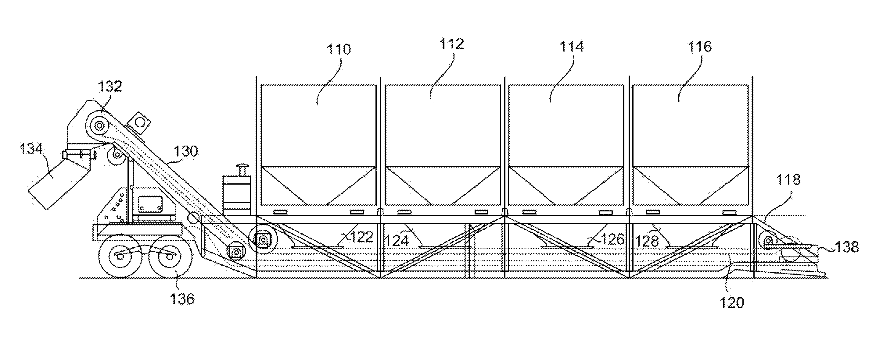
angle of repose of proppant poured into a twenty-foot ISO container, it was evident that much of the volume of such a container was void.
Specifically, the upper ends of twenty-foot ISO container could not be utilized without somehow manipulating or tilting the container as it was filled by a conveyor.
Moreover, when emptying the container, by way of the original bottom hatch, the proppant would pour directly out of the bottom and leave a significant amount of material sitting on the floor of the container.

