Method and apparatus for additive manufacturing

a technology of additive manufacturing and manufacturing method, applied in the field of three-dimensional additive manufacturing method and equipment, can solve problems such as process difficulties

Active Publication Date: 2015-01-01
ARCAM AB
View PDF1 Cites 112 Cited by
  • Summary
  • Abstract
  • Description
  • Claims
  • Application Information

AI Technical Summary

Benefits of technology

[0018]The advantage of this and still other embodiments is that not only the electric and / or the magnetic field from another electron beam source is compensated for but also the distance between two (or more) electron beams as such. Since the electron beams are beams of charged particles they tend to repel each other. When the beams are close to each other the beam position is affected because of the repelling force. By correcting for the misalignment because of this repelling force between two adjacent electron beams, the final result of the three dimensional article may further be improved.
[0019]In still another exemplary and non-limiting embodiment the adjustment because of repelling forces between two adjacent electron beams is performed only in case where the distance between the first and second beams are closer to each other than a predetermined value. The advantage of at least this embodiment is that the manufacturing process time may be kept to a minimum because insignificant compensations may be ignored.

Problems solved by technology

An increase of the build volume may require multiple beam sources which may lead to process difficulties in order to keep the beam spot quality and beam spot positioning equal over the entire build area.

Method used


Image

  • Method and apparatus for additive manufacturing
  • Method and apparatus for additive manufacturing
  • Method and apparatus for additive manufacturing

Examples


Embodiment Construction

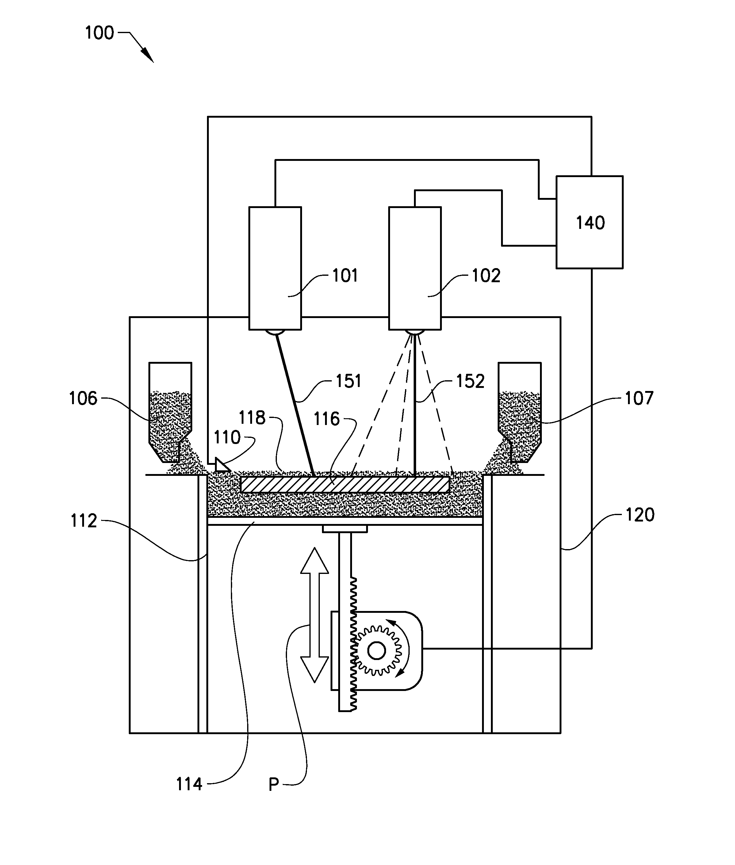
[0031]Various embodiments of the present invention will now be described more fully hereinafter with reference to the accompanying drawings, in which some, but not all embodiments of the invention are shown. Indeed, embodiments of the invention may be embodied in many different forms and should not be construed as limited to the embodiments set forth herein. Rather, these embodiments are provided so that this disclosure will satisfy applicable legal requirements. Unless otherwise defined, all technical and scientific terms used herein have the same meaning as commonly known and understood by one of ordinary skill in the art to which the invention relates. The term “or” is used herein in both the alternative and conjunctive sense, unless otherwise indicated. Like numbers refer to like elements throughout.

[0032]To facilitate the understanding of this invention, a number of terms are defined below. Terms defined herein have meanings as commonly understood by a person of ordinary skill ...


PUM

PropertyMeasurementUnit
accelerating voltageaaaaaaaaaa
electron beam currentaaaaaaaaaa
distanceaaaaaaaaaa

Abstract

A method for forming a three-dimensional article comprising the steps of: applying a model of the three dimensional article, applying a first powder layer on a work table, directing a first electron beam from a first electron beam source over the work table causing the first powder layer to fuse in first selected locations according to the model to form a first cross section of the three-dimensional article, directing a second electron beam from a second electron beam source over the work table, registering at least one setting of the first electron beam source, registering at least one setting of the second electron beam source, correcting the position of the second electron beam depending on the at least one setting of the first electron beam source and the at least one setting of the second electron beam source.

Description

CROSS-REFERENCE TO RELATED APPLICATIONS[0001]This application claims priority to and the benefit of U.S. Provisional Patent Application Ser. No. 61 / 840,936, filed Jun. 28, 2013, the contents of which are hereby incorporated by reference in their entirety.BACKGROUND[0002]1. Technical Field[0003]The present invention relates to a method and apparatus for additive manufacturing of three-dimensional articles.[0004]2. Related Art[0005]Freeform fabrication or additive manufacturing is a method for forming three-dimensional articles through successive fusion of chosen parts of powder layers applied to a worktable via an apparatus.[0006]Such an apparatus may comprise a worktable on which the three-dimensional article is to be formed, a powder dispenser, arranged to lay down a thin layer of powder on the work table for the formation of a powder bed, a ray source for delivering energy to the powder whereby fusion of the powder takes place, elements for control of the ray given off by the ray ...

Claims


Application Information

Patent Timeline
Patent Type & Authority Applications(United States)
IPC IPC(8): B22F3/10B22F3/00
CPCB22F3/003B22F3/1035B22F2003/1057B22F3/1055Y02P10/25B22F10/31B22F10/28B22F12/52B22F10/366B22F12/55B22F12/45
Inventor LJUNGBLAD, ULRIC
Owner ARCAM AB
Why Eureka
Try Eureka