Concentric slave cylinder for a hydraulic clutch actuator

a technology of hydraulic clutch actuator and slave cylinder, which is applied in the direction of reciprocating piston engines, mechanical equipment, engines without rotary main shafts, etc., can solve the problems of comparatively long dwell time, unsuitable reinforcement, and complicated injection molding process,

Inactive Publication Date: 2015-01-08
FTE AUTOMOTIVE GMBH & CO KG
View PDF6 Cites 1 Cited by
  • Summary
  • Abstract
  • Description
  • Claims
  • Application Information

AI Technical Summary

Problems solved by technology

In that connection it has proved that a load-bearing structure of the plastics material is not always created in the flow direction of the molten plastics material behind the mould core so that there is a risk that the cylinder housing during pressure loading of the pressure chamber cracks in the region of the outer cylinder wall and creates a leakage there.
However, the very region mentioned above—which is critical and in which the structure of the plastics material may have an insufficient load-bearing capability as a consequence of the injection-molding process—is additionally subject to external mechanical loading so that such a reinforcement does not appear suitable for avoidance of the mentioned risk of leakage.
However, on the one hand this complicates the injection-molding tool and the actual injection-molding process, because the reinforcement is merely placed in the injection-molding tool, which is of more complicated design with respect to the injection channel duct and ventilation channels, and has to be held there with appropriate orientation.
On the other hand, this causes comparatively lengthy dwell times, which are undesired in mass production, of the injection molded workpiece in the injection molding mould, since the plastics material in the injection-molding mould can cool down and harden

Method used


Image

  • Concentric slave cylinder for a hydraulic clutch actuator
  • Concentric slave cylinder for a hydraulic clutch actuator
  • Concentric slave cylinder for a hydraulic clutch actuator

Examples


Embodiment Construction

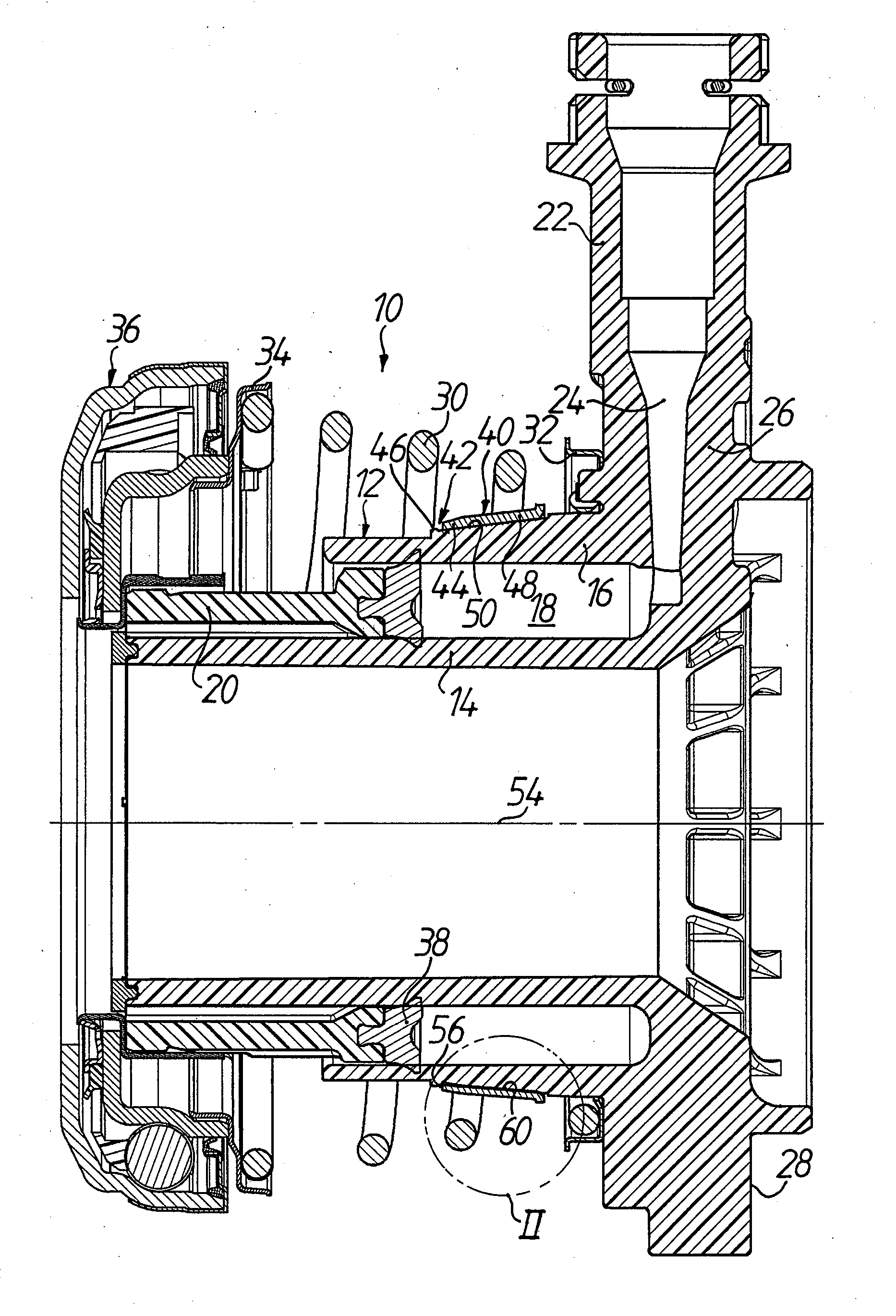
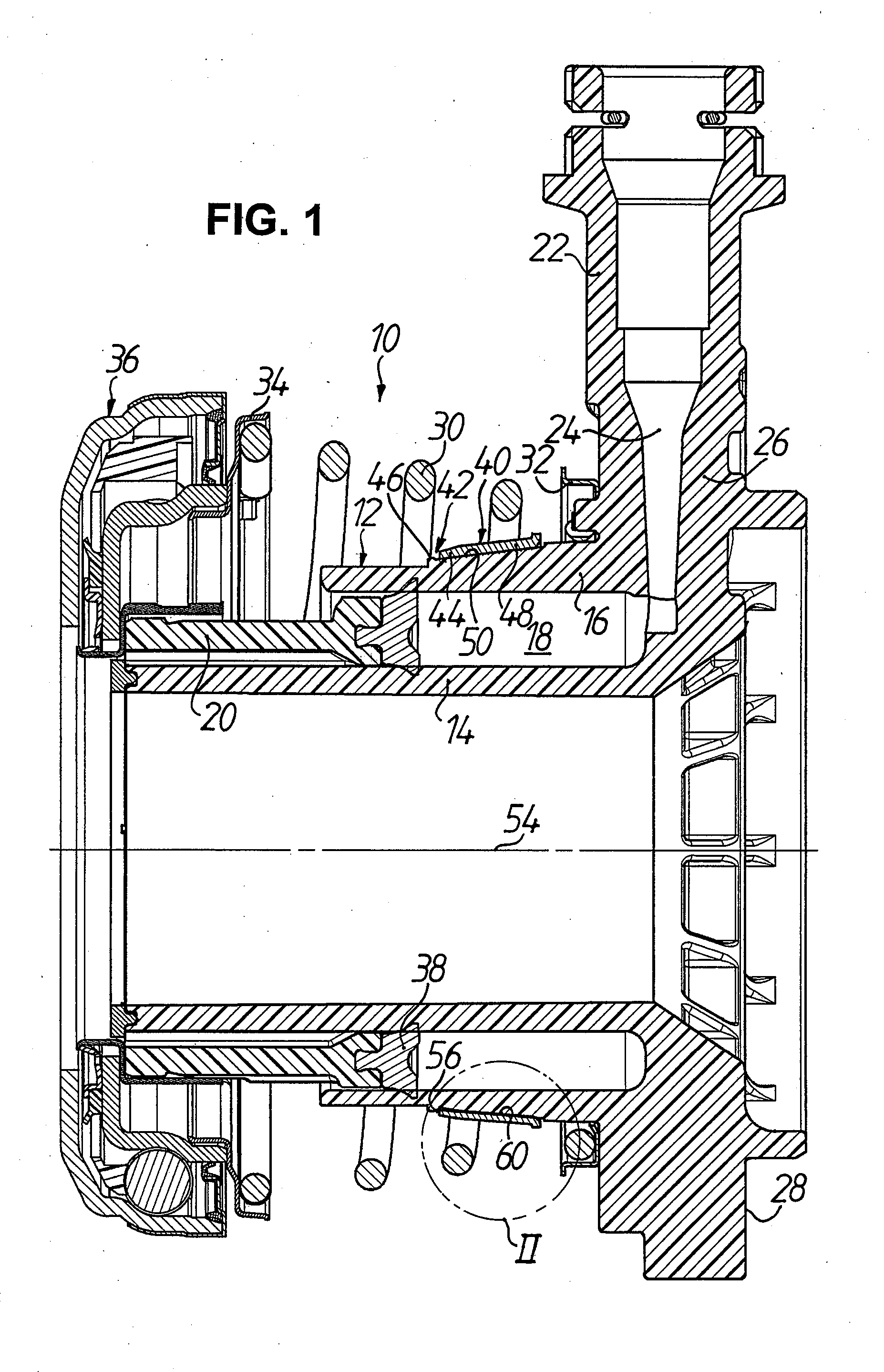
[0024]A concentric slave cylinder 10 for hydraulic clutch actuating means for dry friction clutches is illustrated in FIG. 1 in basic setting in non-mounted state. The concentric slave cylinder 10 has a cylinder housing 12, which is injection-molded from plastics material, for example from GF-filled polyphtalamide, with two concentrically arranged cylinder walls, namely an inner cylinder wall 14 and an outer cylinder wall 16, which bound an annular pressure chamber 18. An annular piston 10 operatively connectible with the clutch (not illustrated) is received in the pressure chamber 18 to be displaceable and can be selectively acted on by a pressure medium via a pressure connecting stub pipe 22 of the cylinder housing 12 in order to release the dry friction clutch by displacement of the annular piston 12. The pressure connecting stub pipe 22 is for this purpose connected with the pressure chamber 18 by way of a channel 14 formed in the cylinder housing 12 so that the pressure medium,...


PUM


Abstract

A central release unit for a hydraulic clutch actuator has a plastic cylinder housing which is produced by injection molding and which has at least one cylinder wall provided, on an outer circumference, with a reinforcement sleeve. The reinforcement sleeve can be fastened to the cylinder wall after the injection molding of the cylinder housing, for which purpose a snap-action connection is provided on a forward end, which faces away from the pressure connection piece, of the reinforcement sleeve. The connection is formed by a radially inwardly bent detent portion of the reinforcement sleeve and by a rib integrally formed on the outer circumference of the cylinder wall. The reinforcement sleeve has a main portion which adjoins the detent portion and which is of conical shape complementary to an outer circumferential surface, which is of conical form in the reinforcement region, of the cylinder wall.

Description

TECHNICAL FIELD[0001]The present invention relates to a concentric slave cylinder for hydraulic clutch actuating means according to the preamble of claim 1. In particular, the invention relates to a concentric slave cylinder of hydraulic clutch actuating means for a motor vehicle friction clutch such as in widespread use in the automobile industry.PRIOR ART[0002]A conventional hydraulic clutch actuating means for motor vehicles has a master cylinder which is connected with a compensating reservoir filled with hydraulic fluid and which can be actuated by way of, for example, a clutch pedal. The master cylinder is hydraulically connected by way of a pressure line with a slave cylinder so that the pressure generated in the master cylinder by pressing down the clutch pedal is transmissible via the fluid column in the pressure line to the slave cylinder. As a result, the release bearing of the friction clutch is acted on by an actuating force from the slave cylinder in order to separate,...

Claims


Application Information

Patent Timeline
IPC IPC(8): F16J10/02
CPCF16J10/02F16D25/083F16D25/02F16D25/08
Inventor GEBERT, STEFANLEHNERT, MATTHIASBRAUN, RUTHARDKUHN, ELMARMOLLER, ERNSTGNYP, JAN
Owner FTE AUTOMOTIVE GMBH & CO KG
Why Eureka
Try Eureka